TV SCART cable
A TV SCART cable allows to connect the CPC/CPCplus to the TV set. This is especially helpful if you couldn't get your hands on a colour monitor or want to use the CPC/CPCplus as a video console in the living room.
Contents
Schematics
Amstrad/Schneider CPC (classic)
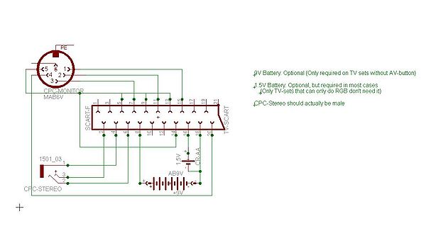
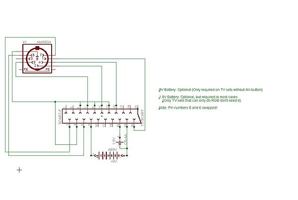
Colour Picture (RGB)
This schematic requires a TV with RGB input on Scart Connector (back in the 8bit era, many TVs have had only Composite input implemented on Scart connectors - nowadays RGB is also supported by DVD players and 3D gaming consoles, which is possibly increasing the chance to find RGB support on modern TVs).
The 9V and 1.5V batteries are optional. Instead of the batteries, you may also extract the voltages from elsewhere (like the CPC supply).
They may be helpful to switch the TV to AV and RGB mode automatically, without needing to activate it via buttons on the remote control. Note that AV input can be usually selected using the remote control, while manual RGB input selection is only available on more recent TVs.
Battery duration: since Pin 16 (RGB input selection) has an input impedance of 75 Ohm, it will drain a common fully charged 1.2V ~2500mAh AA battery in about one week, if left connected permanently to the TV set.
| Pin | Voltage | Function | Note |
| Pin 8 | 9.5V - 12V | enables AV input | 9V is actually a bit too low |
| Pin 16 | 1V - 3V | enables RGB input |
John King's Comments about Scart Connections
The following information relating to the Scart Plug (Euroconnector/Peritel) could be found useful when concocting leads to connect your PCW, CPC or Spectrum +3 to a Television or Video recorder. The data has been checked against a number of technical references and should be correct.
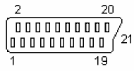 Scart Plug viewed from the Pins.
| PIN | USAGE | ALTERNATIVE NAMES |
|---|---|---|
| 1 | AUDIO RIGHT OUT | AUDIO OUTPUT RIGHT |
| 2 | AUDIO RIGHT IN | AUDIO INPUT RIGHT |
| 3 | AUDIO LEFT OUT | AUDIO OUTPUT LEFT |
| 4 | AUDIO GROUND | AUDIO EARTH |
| 5 | BLUE GROUND | BLUE VIDEO EARTH |
| 6 | AUDIO LEFT IN | AUDIO INPUT LEFT |
| 7 | BLUE | BLUE VIDEO INPUT |
| 8 | STATUS/16-9 | FUNCTION SWITCHING |
| 9 | GREEN GROUND | GREEN VIDEO EARTH |
| 10 | RESERVED | COMMS. DATA LINE 2 |
| 11 | GREEN | GREEN VIDEO INPUT |
| 12 | RESERVED | COMMS. DATA LINE 1 |
| 13 | RED GROUND | RED VIDEO EARTH |
| 14 | FAST BLANKING GROUND | COMMS. DATA GROUND |
| 15 | RED | RED VIDEO INPUT |
| 16 | FAST BLANKING | BLANKING INPUT |
| 17 | VIDEO OUT GROUND | VIDEO OUTPUT EARTH |
| 18 | VIDEO IN GROUND | BLANKING GROUND |
| 19 | VIDEO OUTPUT | COMPOSITE VIDEO OUTPUT |
| 20 | VIDEO INPUT | COMPOSITE VIDEO INPUT |
| 21 | GROUND (COMMON) | PLUG'S METAL SHELL |
John King's Comments about CPC to Television Scart Lead
TELEVISION WITH AV SWITCHING.
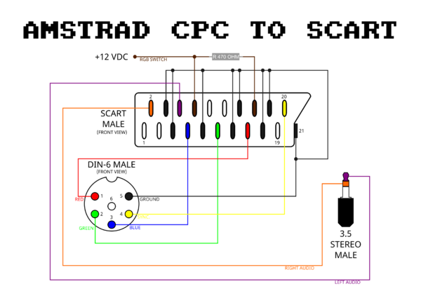
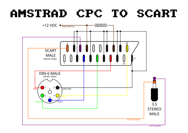
I will start by saying that the tasks to be undertaken on this page are not for those of you without electrical and soldering skills, but for the competent, the following circuit will give a quality picture and stereo sound through a television set from an Amstrad CPC6128, a CPC664 or a CPC464. It has been tested on a number of different makes of TV (with complete success), within, the age range of 1 to 4 years. I have been unable to find anyone admitting to owning a TV without AV switching so no provision has been made in the offered lead for these old crocks.
- PARTS AND TOOLS REQUIRED.
- Scart Plug.
- 6 pin male DIN Plug.
- 3.5mm Stereo Jack Plug.
- 6 feet of six core cable.
- 7 feet of twin screened cable.
- 15 watt Soldering Iron.
- Solder.
- Electrical tape (or cable ties).
- MultiMeter.
- Side cutters, Long nosed pliers and a small screw driver (all of which can be found in any DIY tool box).
Just in case it is not obvious, use the six core cable to connect the DIN plug to the Scart plug and the Twin screened cable to connect the Jack Plug to the Scart Plug. The extra foot of twin screened cable runs from the Din plug (when the two cables are taped together) and plugs into the socket on the side of the CPC machine. Now that the Scart lead has been made up following the above diagram, tape the two leads together (or use the cable ties). Now you will need to turn to adding a suitable power supply to your CPC: Power_Supply_for_CPC_and_CPC_plus
It is well worth the effort of making up a Scart lead and power supply for your CPC machine, as the quality of picture and sound far exceeds that obtained through either a RF connection, via a modulator, or a green/colour monitor. Games are given a new meaning when played using a 28 or 32 inch wide screen TV.
NB Due to the nature of Television design there is a possibility that the lead will not work on every make and model of TV sold thoughout the world.
Foot note. Did you know what DIN indicates in the names of assortment of plugs and sockets use by most of our beloved games machines -- no it is not Drug Identification Number but in fact an acronym for Deutsche IndustriNorm --- so now you know.
© J.R.P.King. Updated 30th September 2003
Black & White Monochrome Picture
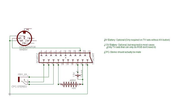
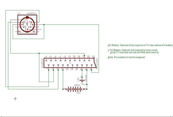
This schematic passes Luminance to the TVs Composite Input. It's giving only a monochrome picture, the advantage is that it works on nearly all TVs including such without RGB input.
Doing this would be useful only for using the TV as replacement for the GT64/GT65 monitor.
Bug: The 1.5V battery shown in the mono schematic is nonsense; for composite, Pin16 should be wired to GND, not to 1.5V.
Alternative RGB Wiring
Amstrad CPCplus (In theory also GX4000, but it has its own SCART outlet)
Colour Picture (RGB)
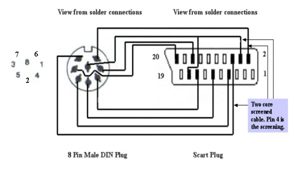
John King's Comments about CPC Plus to Television Scart Lead
TO TELEVISION WITH AV SWITCHING.
Perhaps I should start by saying that the tasks to be undertaken on this page are not for those of you without electrical and soldering skills, but for the competent, the following circuit will give a quality picture and stereo sound through a television set from an Amstrad CPC6128 Plus, a CPC464 Plus and GX4000. The lead has been tested on a number of different makes of TV (with complete success), within, the age range of 1 to 4 years. I have been unable to find anyone admitting to owning a TV without AV switching so no provision has been made in the offered lead for these old obsolete televisions.
- PARTS AND TOOLS REQUIRED.
- Scart Plug (also known as an Euroconnector or Peritel Plug).
- 8 pin male DIN Plug.
- 6 feet of six core cable.
- 6 feet of twin screened cable.
- 15 watt Soldering Iron.
- Solder.
- Electrical tape (or cable ties).
- MultiMeter.
- Side cutters, Long nosed pliers and a small screw driver (all of which can be found in any DIY tool box).
Just in case it is not obvious, use the six core cable to connect the DIN plug video/RGB connections to the Scart plug and the twin screened cable is for the sound connections to the Scart Plug. Now that the Scart lead has been made up following the above diagram, tape the two leads together (or use cable ties). Now you will need to turn to making a suitable power supply for your CPC Plus/GX4000 machine.
The GX4000 offers a Scart socket for connection to a TV (The Pin connections are listed wrongly in it's manual!). You will need to use the power supply (if not already defective) as issued with the machine, when using a Scart lead.
POWER SUPPLY.
You will need to find a Power Supply Unit giving a 5 volt regulated DC output. See this Wiki article for more information: Power_Supply_for_CPC_and_CPC_plus
It is well worth the effort of making up a Scart lead and power supply unit for your CPC Plus/GX4000 machines, as the quality of picture and sound far exceeds that obtained from a Black/White or colour monitor. Games are given a new meaning when played using a 32 inch wide screen Television.
NB Due to the nature of Television design there is a possibility that the lead will not work on every make and model of TV sold thoughout the world.
© J.R.P.King. Updated 27th July 2002.
Black & White Monochrome Picture
Additional Resistors
Info from OCT: "I recall that when Amstrad Action came up with the proposal for a SCART cable back in issue AA41, numerous readers wrote in suggesting that resistors (most commonly: slightly below 330 ohms) should be connected "in series to the colour signals [...] for improving picture quality" (AA45, June 1989, FORUM, p. 23), so they seem to have appeared overblown in comparison to the CTM644s' back in the day."
The goal of that improvement is unknown - it might alter the medium-to-bright ratio, or, it might be simply intended to reduce the overall brightness (such like when the CPC picture appears brighter then normal TV programs). The voltage/brightness output by the CPC is actually higher than normal SCART voltages, however, the voltage drops when the TV applies load to the RGB pins; that load may vary from TV to TV, and so, the resistors may be needed only on some TVs, but not on others.
Videos
A SCART cable howto: https://www.youtube.com/watch?v=yNT36Tf6PxU
See also
- Connector:Monitor - Video output on the CPC
- Power_Supply_for_CPC_and_CPC_plus
