AMRAM2
(All references to I in this documented refer to Kevin Thacker)
AMRAM2 is a ROM board from Silicon Systems.
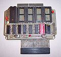
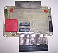
The AMRAM has two PCBs sitting on top of each other, joined with a rigid connector.
On the bottom is passthrough for other expansion connectors and a 3V square lithium battery. (The exact replacement battery (40LF220 SAFT Memoguard 3.0V Lithium Encapsulated Cell) is expensive @ £19.49 each. It *is* possible to fit a PC CMOS compatible lithium battery (CR2032) and holder, but it's not as neat and there is not a lot of space between the two pcb boards of the Amram)
On the top, 32K RAM (contents are held by lithium battery so can survive a reset or power off), which can be programmed like ROM and occupies two ROM positions (1 and 2) and also sockets for expansion ROMs 3,4,5 and 6.
There is a bank of DIP switches to enable/disable ROM slots, a switch to enable/disable writes to 32K RAM (left side of top pcb), a LED to indicate RAM is ready to write and a switch to reset computer (right side of top pcb).
It seems the first few batches of these were distributed without boxes, so you had to provide your own. A suitable box can be made from a "General purpose ABS Enclosure" which is a black plastic box designed for electronics. This is the type of box shown in the picture.
Came with software to program it.
This came after the AMRAM which was 16K ram on a board which could be programmed and which occupied ROM slot 5. More details when I can find them in my documents.
Details of battery in AMRAM 2:
40LF220 SAFT Memoguard 3.0V Lithium Encapsulated Cell
Type: Lithium Manganese Dioxide.
Voltage: 3.0 V.
Height: 28 mm.
Width: 25.4 mm.
Thickness:  6.7 mm.
With modification (old battery removed, a socket and some wires added) a CR2032 battery can be used.
Technical
Documentation states to use port FBF0 to write to the AMRAM2. This is advised to avoid clashing with other hardware. I tested various I/O addresses and came to this port decoding:
A15-A0: xxxx10111111xxxx
When writing data only bit 0 of the data is significant all other bits are ignored. This has been confirmed with testing. If bit 0 is 1, then AMRAM is activated and writing to it's RAM is possible. If bit is 0, then AMRAM is not active and writing has no effect.
The ROM select is decoded in the normal way: Bit 13=0 of the address and all other bits of the address are ignored.
In addition the ROM select IDs are decoded fully, there is no repeat across the 256 ROM range. The ROMs only exist in their designated slots (i.e. 1 only exists at position 1 and no others).
Amram2's RAM can be written *WITHOUT* enabling the upper ROM. It is only necessary to enable writing to the AMRAM RAM using FBF0 and then to select ROM 1 or 2 as needed. Writes go to CPC RAM AND Amram2's RAM.
When writing Amram2 must be enabled using FBF0 *BEFORE* selecting the page with DFxx.
For fully reliable operation, use fbf0=0 then re-select rom with DFxx to ensure writing is fully disabled.
When reading as a ROM it is not necessary to use port FBF0. The normal ROM select procedure applies.
On reset or power cycle Amram2 write protect via FBF0 is disabled.
Pictures
Download
Amram 2 user manual: File:Amram2.pdf


