ABBA switch
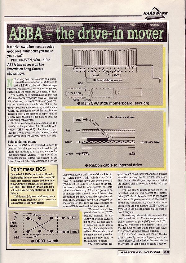
ABBA Switch for Classic CPC
ABBA Switch for Plus CPC
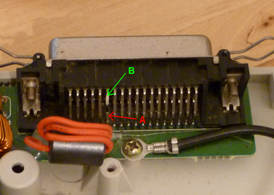
Because the pinouts are slightly different on the CPC6128 Plus, the description above cannot be used. I've chosen safe places to make the connects so that this modification can be safely carried out by those who may be worried about damaging their Plus due to a lack of soldering skills. To access the external DS1 signal, you can simply cut the pin at the rear of the 36 way connector. Pin 11 (the sixth pin from the left) should be cut roughly in the centre of the pin. The part of the pin still connected to the PCB is pin A and pin B is the other half which should be still connected to the actual socket.
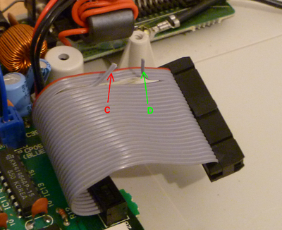
The internal drive select DS0 is pin 4, the fourth wire from the top (starting at the red wire). Carefully separate this wire from flat cable using a blade and cut this wire in the centre also. The wire on the PCB side is pin C and the wire connected to the drives connector is pin D.
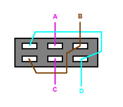
The pins marked A and C are the signal sources and should be connected to the two inner pins of a DPDT toggle switch. The pins marked B and D should be connected to the outer pins of the switch which have been cross connected as shown below.
When all connections have been made, mount the switch in the position of your choice. I chose to put the switch directly behind the internal driver, but the Plus has lots of other spare surfaces for switches unlike the the classic CPC.


