Difference between revisions of "DDI-1 with 64 KB"
(Created page with "This project shows how to replace the 16 KB ROM of the DDI-1 floppy disc controller of the CPC464 with a 64 KB ROM in a way which provides four 16 KB ROMs. These four ROMs are ac...") |
|||
| Line 24: | Line 24: | ||
Link IC110 pin 13 to IC109 pin 1 (D2), show as a red wire on the circuit diagram. | Link IC110 pin 13 to IC109 pin 1 (D2), show as a red wire on the circuit diagram. | ||
Add a 74LS74 to latch D0 & D1, clock driven from IC107 pin 8. The outputs of the 74LS74 drive A14 & A15 of a 64 KB EPROM. | Add a 74LS74 to latch D0 & D1, clock driven from IC107 pin 8. The outputs of the 74LS74 drive A14 & A15 of a 64 KB EPROM. | ||
| + | |||
| + | |||
| + | |||
| + | |||
| + | |||
| + | |||
| + | |||
| + | |||
| + | |||
| + | |||
| + | |||
| + | |||
| + | |||
| + | |||
| + | |||
| + | |||
| + | |||
| + | |||
| + | |||
| Line 30: | Line 49: | ||
Link IC110 pin 13 to IC109 pin 1 (D2), show as a red wire on the circuit diagram. | Link IC110 pin 13 to IC109 pin 1 (D2), show as a red wire on the circuit diagram. | ||
| − | [[Image:DDI164Kc.png| | + | [[Image:DDI164Kc.png|360px|centre]] |
Wire the 74LS74 as shown: | Wire the 74LS74 as shown: | ||
| − | [[Image:DDI164Kd.png| | + | [[Image:DDI164Kd.png|360px|centre]] |
The CLK signal comes from here: | The CLK signal comes from here: | ||
| − | [[Image:DDI164Ke.png| | + | [[Image:DDI164Ke.png|360px|centre]] |
== Disclaimer == | == Disclaimer == | ||
Latest revision as of 15:57, 18 September 2012
This project shows how to replace the 16 KB ROM of the DDI-1 floppy disc controller of the CPC464 with a 64 KB ROM in a way which provides four 16 KB ROMs. These four ROMs are accessible at the same time and have different ROM numbers.
To archive this target an additional chip is needed, as well as a single track must be cut on the PCB. This solution will provide ROMs at the ROM selects 4, 5, 6 and 7. At 7 you will usually find AMSDOS.
How to do it?
Program a 27C512 EPROM with the data for the four ROMs:
- &0000-&3FFF - ROM 4
- &4000-&7FFF - ROM 5
- &8000-&BFFF - ROM 6
- &c000-&FFFF - ROM 7 (e.g. AMSDOS, X-DDOS or PARADOS)
You can also burn FutureOS in the four ROMs.
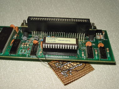
When inserting the ROM into the socket of the DDI-1, bend pin 1 (A15) and 27 (pin 14) so the EPROM pins don't connect to the socket, they need to be connected to the 74LS74.
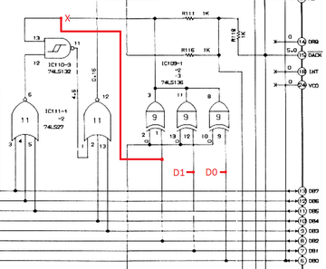
Cut the track between IC110 pin 13 and IC109 (shown as an X on the circuit diagram). That means you change the input of IC110 pin 13, link it to D2 (IC109 pin 1). The ROM latch (IC112-1) then get set for ROMs 4-7.
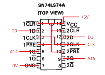
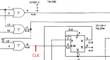
Link IC110 pin 13 to IC109 pin 1 (D2), show as a red wire on the circuit diagram. Add a 74LS74 to latch D0 & D1, clock driven from IC107 pin 8. The outputs of the 74LS74 drive A14 & A15 of a 64 KB EPROM.
Step by Step
Cut the track between IC110 pin 13 and IC109 (shown as an X on the circuit diagram) Link IC110 pin 13 to IC109 pin 1 (D2), show as a red wire on the circuit diagram.
Wire the 74LS74 as shown:
The CLK signal comes from here:
Disclaimer
This project was realized by IanS and put into the CPCWiki by TFM. Not one of us can be made responsible for any kind of destruction or other problems. You do it on your own risk.


