Difference between revisions of "Upgrading a Dk'tronics RAM Expansion"
(→The Conversion) |
Jonathanen (Talk | contribs) (→Conversion to Silicon Disc) |
||
| (2 intermediate revisions by 2 users not shown) | |||
| Line 19: | Line 19: | ||
As you can see, Dk'tronics were nice enough to use the same PCB for both the 64K and 256K version and even put the RAM and PAL ICs in sockets, but two ICs are missing in the bottom right corner. | As you can see, Dk'tronics were nice enough to use the same PCB for both the 64K and 256K version and even put the RAM and PAL ICs in sockets, but two ICs are missing in the bottom right corner. | ||
| − | |||
== Parts List == | == Parts List == | ||
| Line 51: | Line 50: | ||
| − | The next thing we need to do is change the jumper settings. At the top right | + | The next thing we need to do is change the jumper settings. At the top right corner you will see two small vertical wire loops next to each other. These need to be removed and two new bridges added to connect the points horizontally as shown below. |
| Line 74: | Line 73: | ||
| − | In the top left corner you will see two vertical rows of 5 holes (slightly obscured by a resistor). By connecting the top left hole to the bottom right hole, the expansion will then be mapped to banks 4 to 7. This will allow you to use the device as a Silicon disc or to connect two RAM expansions at the same time (only one should be set to banks 4 to 7). You can connect the two holes with a small piece of wire, for permanent conversion, or with a switch so that the device can be switched back and forth between the two modes. | + | In the top left corner you will see two vertical rows of 5 holes (slightly obscured by a resistor). By connecting the top left hole to the bottom right hole, the expansion will then be mapped to banks 4 to 7. This will allow you to use the device as a Silicon disc or to connect two RAM expansions at the same time (only one should be set to banks 4 to 7). You can connect the two holes with a small piece of wire, for permanent conversion, or with a [[Dk%27tronics_Memory_Expansion_Gallery#256k_RAM_Silicon_Disc_for_CPC_464.2F664_-_modified_.28without_separate_ROM_cartridge.29|switch]] so that the device can be switched back and forth between the two modes. |
Latest revision as of 15:57, 30 September 2020
Contents
Description
The following is a description on how to convert a 64K Dk'tronics Memory Expansion to 256K and how to change its bank mapping to allow it to be used as a silicon disc.
Warning / Disclaimer
Although I have taken the utmost care preparing this documentation, I do not guarantee that it is error free and I accept no responsibility for damage to anyone’s CPC, other personal equipment or injury inflicted on you or others.
The Device
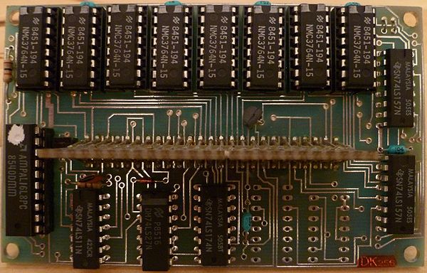
When you open your 64K expansion it should look something like this. There were several different routing layout versions available, but the differences have no effect on the modifications shown here.
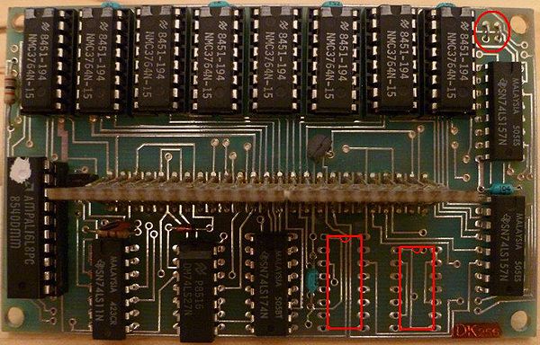
As you can see, Dk'tronics were nice enough to use the same PCB for both the 64K and 256K version and even put the RAM and PAL ICs in sockets, but two ICs are missing in the bottom right corner.
Parts List
These are the parts you'll need for the Conversion:
| Component | Quantity |
| RAM = 41256-15 (or faster) | 8 |
| 74LS74 | 1 |
| 74LS153 | 1 |
The 74LS74 and 74LS153 are both widely available and very cheap because they are still in production. Although the 41256 isn't produced any more, they were used in many computers and other devices in the 80's and 90's and can be easily and cheaply found in many online auction sites.
The Conversion
The first thing you need to do is carefully remove the 8 64K RAM ICs (Usually Part No. NMC3764N-15) and store them somewhere safe (you never know when you might need them).
Next you need to add the two missing ICs. These can be socketed or directly soldered to the PCB, depending on how good your soldering skills are. The 74LS153 should be soldered into the left space with the notch at the top (like the other ICs are) and the same for the 74LS74 in the right space.
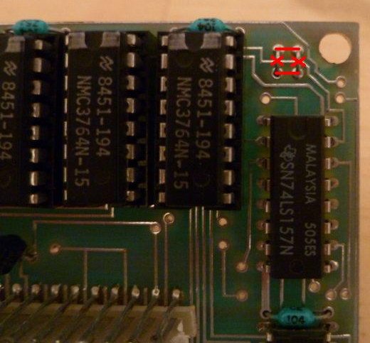
The next thing we need to do is change the jumper settings. At the top right corner you will see two small vertical wire loops next to each other. These need to be removed and two new bridges added to connect the points horizontally as shown below.
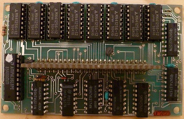
When all this has been done, you can insert the 8 256K RAM ICs. It should then look something like this.
Now you can re-assemble the device and test it using the Dk'tronics Banking Software found here: Dk'tronics Memory Expansion or TFMs RAM check software found here: Media:4_MB_E-RAM_Test.zip
Conversion to Silicon Disc
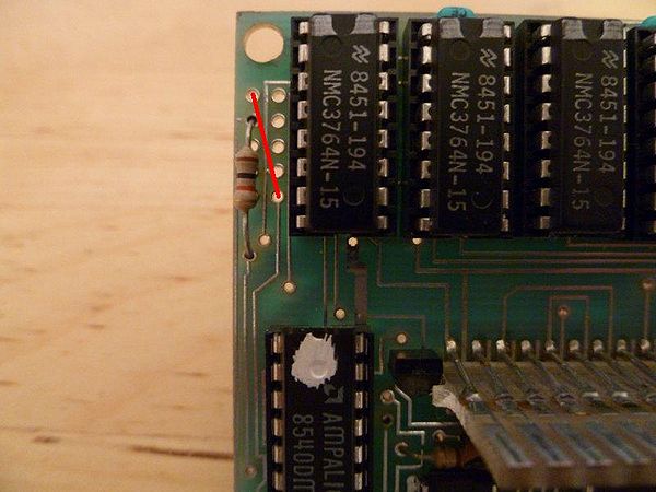
Your Expansion now works as a 256K RAM Expansion which is mapped to banks 0 to 3. If you wish to use your expansion as a Silicon disc or you own two 256K Expansions and wish to connect both at the same time to get 512K External RAM, you can add one further feature to allow this.
In the top left corner you will see two vertical rows of 5 holes (slightly obscured by a resistor). By connecting the top left hole to the bottom right hole, the expansion will then be mapped to banks 4 to 7. This will allow you to use the device as a Silicon disc or to connect two RAM expansions at the same time (only one should be set to banks 4 to 7). You can connect the two holes with a small piece of wire, for permanent conversion, or with a switch so that the device can be switched back and forth between the two modes.
Bryce.
