Difference between revisions of "CPC Prototypes"
(→The 'Version 0' Prototype: Added X-Ray view) |
|||
| (11 intermediate revisions by 5 users not shown) | |||
| Line 1: | Line 1: | ||
| − | |||
| − | |||
== History & Overview == | == History & Overview == | ||
| + | |||
| + | == The 'Version 0' Prototype == | ||
| + | |||
| + | The 'Version 0' motherboard prototype was the motherboard originally designed for the MOS 6502 microprocessor. | ||
| + | That board is owned by Roland Perry, the Amstrad CPC 464 project manager by 1983. | ||
| + | The board was shown by Roland in Retroalacant 2023, Alicante (Spain). | ||
| + | |||
| + | <gallery caption="Pictures of the Amstrad CPC 464 'Version 0' motherboard prototype"> | ||
| + | Image:Amstrad cpc 464 v0 prototype components side.jpg|The Amstrad CPC 464 Version 0 motherboard prototype, components side | ||
| + | Image:Amstrad cpc 464 v0 prototype soldering side.jpg|The Amstrad CPC 464 Version 0 motherboard prototype, soldering side | ||
| + | Image:CPC464_V0_PCB_Top.jpg|V0 prototype board, component side | ||
| + | Image:CPC464_V0_PCB_Bottom.jpg|V0 prototype board, solder side | ||
| + | Image:CPC464_V0_PCB_Composite_View.jpg|V0 prototype board, X-Ray view | ||
| + | </gallery> | ||
== The Arnold == | == The Arnold == | ||
| Line 9: | Line 21: | ||
== The Gate Array Simulator == | == The Gate Array Simulator == | ||
| − | The [[Gate Array]] was the only component of the Amstrad CPC, which was not a standard one but developed by Amstrad. Before it could be produced as a single chip, they had to make tests with a prototype, | + | The [[Gate Array]] was the only component of the Amstrad CPC, which was not a standard one but developed by Amstrad. Before it could be produced as a single chip, they had to make tests with a prototype, which was a single print on top of the actual motherboard. Aside from the Gate Array logic, the PCB does also contain the 32K BIOS ROM (stored in four 8K EPROMs). |
<gallery caption="Pictures of the Gate Array prototype"> | <gallery caption="Pictures of the Gate Array prototype"> | ||
Image:GA motherboard.JPG|The gate array as a complete additional PCB board | Image:GA motherboard.JPG|The gate array as a complete additional PCB board | ||
Image:Inside GA.JPG|Another picture of the gate array prototype | Image:Inside GA.JPG|Another picture of the gate array prototype | ||
| + | Image:GateArraySimulator_13006-7_PCB_Top.jpg|Component side<br>(c) Jorge Selfa | ||
| + | Image:GateArraySimulator_13006-7_PCB_Bottom.jpg|Solder Side<br>(c) Jorge Selfa | ||
</gallery> | </gallery> | ||
| Line 21: | Line 35: | ||
The first cases of the [[CPC]] 464 had a grey colour instead of the later used black colour. Probably these prototypes have been sent to several software houses to enable them to start developing CPC software before the computers' release. | The first cases of the [[CPC]] 464 had a grey colour instead of the later used black colour. Probably these prototypes have been sent to several software houses to enable them to start developing CPC software before the computers' release. | ||
| + | According to [[Your Computer]], Issue 11-1984, [[:File:YourComputer841100059.jpg|page 59]], Amstrad did supply software houses with CPCs since December 1983 (the CPC464 was officially launched about half a year later, in June 1984). | ||
| + | |||
| + | <gallery caption="CPC 464 Prototype pictures by Jorge Selfa."> | ||
| + | Image:CPC464_Prototype.jpg | ||
| + | Image:CPC464_Prototype_2.jpg | ||
| + | Image:CPC464_Prototype_3.jpg | ||
| + | Image:CPC464_Prototype_Case_Top_Outer.jpg | ||
| + | Image:CPC464_Prototype_Case_Top_Inner.jpg | ||
| + | Image:CPC464_Prototype_Case_Bottom_Inner.jpg | ||
| + | Image:CPC464_Prototype_Case_Bottom_Outer.jpg | ||
| + | Image:CPC464_Prototype_Keyboard_Top.jpg | ||
| + | Image:CPC464_Prototype_Keyboard_Bottom.jpg | ||
| + | Image:CPC464_Prototype_Z70100_PCB_Top.jpg | ||
| + | Image:CPC464_Prototype_Z70100_PCB_Bottom.jpg | ||
| + | Image:CPC464_Prototype_Tape_Deck_Top.jpg | ||
| + | Image:CPC464_Prototype_Tape_Deck_Bottom.jpg | ||
| + | Image:CPC464_Prototype_PSU.jpg | ||
| + | </gallery> | ||
| − | [[Category:CPC History]] | + | [[Category:CPC History|*]][[Category:CPC Internal Components|*]] |
Latest revision as of 03:03, 6 October 2023
Contents
History & Overview
The 'Version 0' Prototype
The 'Version 0' motherboard prototype was the motherboard originally designed for the MOS 6502 microprocessor. That board is owned by Roland Perry, the Amstrad CPC 464 project manager by 1983. The board was shown by Roland in Retroalacant 2023, Alicante (Spain).
- Pictures of the Amstrad CPC 464 'Version 0' motherboard prototype
The Arnold
Arnold was the internal code name of the first Amstrad CPC prototype, which was built around a MOS 6502 CPU. As they choosed the Z80 based programming language Locomotive BASIC as a part of the core system, Amstrad decided to replace the 6502 with the Zilog Z80. One of the "Arnold" prototypes was sold via Ebay in 2005.
The Gate Array Simulator
The Gate Array was the only component of the Amstrad CPC, which was not a standard one but developed by Amstrad. Before it could be produced as a single chip, they had to make tests with a prototype, which was a single print on top of the actual motherboard. Aside from the Gate Array logic, the PCB does also contain the 32K BIOS ROM (stored in four 8K EPROMs).
- Pictures of the Gate Array prototype
The Grey Amstrad
The first cases of the CPC 464 had a grey colour instead of the later used black colour. Probably these prototypes have been sent to several software houses to enable them to start developing CPC software before the computers' release.
According to Your Computer, Issue 11-1984, page 59, Amstrad did supply software houses with CPCs since December 1983 (the CPC464 was officially launched about half a year later, in June 1984).
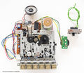
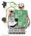
- CPC 464 Prototype pictures by Jorge Selfa.


