Difference between revisions of "Gate Array"
(→Palette sorted by Firmware Colour Numbers) |
|||
| (94 intermediate revisions by the same user not shown) | |||
| Line 2: | Line 2: | ||
Also designated as Video gate Array (VGA, not to be confused with IBM PC compatible graphic card spec). | Also designated as Video gate Array (VGA, not to be confused with IBM PC compatible graphic card spec). | ||
| + | |||
| + | <br> | ||
== Introduction == | == Introduction == | ||
| − | The | + | The Gate Array is a specially designed chip exclusively for use in the Amstrad CPC and was designed by Amstrad plc. |
| − | In the CPC+ system, the functions of the Gate | + | In the CPC+ system, the functions of the Gate Array are integrated into a single [[ASIC|ASIC]]. When the ASIC is "locked", the extra features are not available and the ASIC operates the same as the Gate Array in the CPC allowing programs written for the CPC to work on the Plus without modification. The ASIC must be "un-locked" to access the new features. |
| − | In the [[KC Compact]] system, the functions of the Gate | + | In the [[KC Compact]] system, the functions of the Gate Array are "emulated" in TTL chips, [[CIO Overview|CIO]], and its color translation EPROM. |
| − | In the "cost-down" version of the CPC6128, the functions of the Gate | + | In the "cost-down" version of the CPC6128, the functions of the Gate Array are integrated into a ASIC. |
| − | + | <br> | |
== What does it do? == | == What does it do? == | ||
The Gate Array is responsible for the display (colour palette, resolution, horizontal and vertical sync), interrupt generation and memory arrangement. | The Gate Array is responsible for the display (colour palette, resolution, horizontal and vertical sync), interrupt generation and memory arrangement. | ||
| + | |||
| + | <br> | ||
| + | |||
| + | == Interrupt management == | ||
| + | |||
| + | Interrupts on the CPC are created by the Gate Array based on settings from the CRTC. The Gate Array has an internal counter (R52) that counts from 0 to 51, incrementing after each HSYNC signal. | ||
| + | |||
| + | R52 will return to 0 and the Gate Array will send an interrupt request on any of these conditions: | ||
| + | * When it exceeds 51 | ||
| + | * By setting bit4 of the RMR register of the Gate Array to 1 | ||
| + | * At the end of the 2nd HSYNC after the start of the VSYNC | ||
| + | |||
| + | When the Gate Array sends an interrupt request: | ||
| + | *If the interrupts were authorized at the time of the request, then bit5 of R52 is cleared (but R52 was reset to 0 anyway) and the interrupt takes place | ||
| + | *If interrupts are not authorized, then the R52 counter continues to increment and the interrupt remains armed (the Gate Array then maintains its INT signal). When interrupts are enabled (using the EI instruction) and '''after the instruction that follows EI''' (so not immediately after EI), bit5 of R52 is cleared and the interrupt takes place | ||
| + | |||
| + | Note: On Amstrad Plus, the Gate Array is not the sole generator of interrupts. The 3 DMA sound channels are each able to trigger an interrupt. The ASIC also offers a programmable raster interrupt register (PRI) that can be used instead of the normal raster interrupt mechanism. And it provides an interrupt vector register (IVR) for vectorized interrupts. | ||
| + | |||
| + | <br> | ||
| + | |||
| + | == CSYNC signal == | ||
| + | |||
| + | On CPC, the HSYNC and VSYNC signals are received from the [[CRTC]]. These signals are then modified by the Gate Array as C-HSYNC and C-VSYNC and then merged into a single CSYNC signal that will be sent to the display. | ||
| + | |||
| + | When CRTC HSYNC is active, the Gate Array immediately outputs the palette colour black. If the HSYNC is set to 14 characters then black will be output for 14µs. | ||
| + | |||
| + | If a graphics mode change is pending, the HSYNC pulse width needs to be at least 2µs for Gate Array to change the graphics mode. | ||
| + | |||
| + | The HSYNC is modified before being sent to the monitor. It happens 2µs after activation of the CRTC HSYNC and stay a maximum of 4µs (signal is cut short if HSYNC width is greater than 6). | ||
| + | |||
| + | For example, if CRTC R2=46, and CRTC HSYNC width is 14 chars then monitor hsync starts at 48 and lasts only until 51 included. | ||
| + | |||
| + | The same logic applies to VSYNC, with lines instead of chars. The Gate Array VSYNC is considered complete when the 26th line has been processed. Then the Gate Array stops outputting the palette colour black. | ||
| + | |||
| + | The Gate Array uses 2 internal counters to create its CSYNC signal: | ||
| + | * H06 which counts the number of CRTC characters processed during an HSYNC. H06 is incremented by the Gate Array for each CRTC character when CRTC HSYNC is active. The Gate Array activates the C-HSYNC signal when H06 reaches 2, and changes its graphics mode if a change was pending. It deactivates this signal when H06 reaches 6. | ||
| + | * V26 which counts the number of HSYNCs occuring during a VSYNC. V26 is incremented by the Gate Array when the CRTC signals an end of HSYNC. The Gate Array activates the C-VSYNC signal when V26 reaches 2. It deactivates this signal when V26 reaches 6. | ||
| + | |||
| + | The HSYNC signal from the CRTC is 0 when inactive and 1 when active. Same for VSYNC. | ||
| + | |||
| + | C-HSYNC and C-VSYNC are composited using the XNOR function. The resulting CSYNC signal produced by the Gate Array is 1 when inactive and 0 when active. | ||
| + | |||
| + | On a CPC monitor, the CSYNC is rendered in "absolute black". It is darker than the palette colour black output by the Gate Array. The electron beam is basically turned off. Turning up the brightness level won't make it any brighter. | ||
| + | |||
| + | <br> | ||
== Controlling the Gate Array == | == Controlling the Gate Array == | ||
| Line 23: | Line 70: | ||
The gate array is controlled by I/O. The gate array is selected when bit 15 of the I/O port address is set to "0" and bit 14 of the I/O port address is set to "1". The values of the other bits are ignored. However, to avoid conflict with other devices in the system, these bits should be set to "1". | The gate array is controlled by I/O. The gate array is selected when bit 15 of the I/O port address is set to "0" and bit 14 of the I/O port address is set to "1". The values of the other bits are ignored. However, to avoid conflict with other devices in the system, these bits should be set to "1". | ||
| − | The recommended I/O port address is & | + | The recommended I/O port address is &7Fxx. |
| − | The function to be performed is selected by writing data to the Gate | + | The function to be performed is selected by writing data to the Gate Array, the first bits of the data define the function selected (see table below). It is not possible to read from the Gate Array. |
{|{{Prettytable|width: 700px; font-size: 2em;}} | {|{{Prettytable|width: 700px; font-size: 2em;}} | ||
|- | |- | ||
| − | | | + | !colspan=4| 8bit command |
| + | !rowspan=2| Machine | ||
| + | !rowspan=2| Register | ||
| + | !rowspan=2| Description | ||
| + | !rowspan=2| Chip | ||
|- | |- | ||
| − | + | ! 7 | |
| + | ! 6 | ||
| + | ! 5 | ||
| + | ! 4..0 | ||
|- | |- | ||
| − | | 0 || | + | | 0 || 0 || x || style="text-align: center;" | n || All || PENR || Select a color register || Gate Array |
|- | |- | ||
| − | | 1 || | + | | 0 || 1 || x || style="text-align: center;" | n || All || INKR || Change the value of the currently selected color register || Gate Array |
|- | |- | ||
| − | | 1 || | + | | 1 || 0 || 0 || style="text-align: center;" | n || All || RMR || Control Interrupt counter, ROM mapping and Graphics mode || Gate Array |
|- | |- | ||
| + | | 1 || 0 || 1 || style="text-align: center;" | n || All || RMR || ''Ghost register'' || Gate Array (CPC) or locked ASIC (Plus) | ||
| + | |- | ||
| + | | 1 || 0 || 1 || style="text-align: center;" | n || Plus || RMR2 || ASIC & Advanced ROM mapping || Unlocked ASIC | ||
| + | |- | ||
| + | | 1 || 1 ||colspan=2 style="text-align: center;" | n || All || MMR || RAM memory mapping || PAL | ||
|} | |} | ||
| − | == | + | The MMR register is not available in the Gate Array, but is performed by a device at the same I/O port address location. |
| + | |||
| + | In the CPC464, CPC664 and KC compact, MMR is performed in an external memory expansion (e.g. Dk'Tronics 64K RAM Expansion), if this expansion is not present then MMR is not available. | ||
| + | |||
| + | In the CPC6128, MMR is performed by a [[PAL16L8|PAL]] located on the main PCB, or an external memory expansion. | ||
| + | |||
| + | In the 464+ and 6128+, MMR is performed by the ASIC or an external memory expansion. Please read the document on RAM management for more information. | ||
| + | |||
| + | <br> | ||
| + | |||
| + | == Registers == | ||
| − | + | Note: The Plus palette capabilities are only accessible through the ASIC I/O page. Registers PENR and INKR are not needed in that case. | |
| − | == Register | + | === Register PENR (Select a color register) === |
When bit 7 and bit 6 are set to "0", the remaining bits determine which pen is to have its colour changed. When bit 4 is set to "0", bits 3 to 0 define which pen is to be selected. When bit 4 is set to "1", the value contained in bits 3-0 is ignored and the border is selected. | When bit 7 and bit 6 are set to "0", the remaining bits determine which pen is to have its colour changed. When bit 4 is set to "0", bits 3 to 0 define which pen is to be selected. When bit 4 is set to "1", the value contained in bits 3-0 is ignored and the border is selected. | ||
| Line 53: | Line 122: | ||
Each mode has a fixed number of pens. Mode 0 has 16 pens, mode 1 has 4 pens and mode 2 has 2 pens. | Each mode has a fixed number of pens. Mode 0 has 16 pens, mode 1 has 4 pens and mode 2 has 2 pens. | ||
| − | === Summary === | + | ==== Summary ==== |
{|{{Prettytable|width: 700px; font-size: 2em;}} | {|{{Prettytable|width: 700px; font-size: 2em;}} | ||
| Line 59: | Line 128: | ||
| ''Bit'' || ''Value'' || ''Function'' | | ''Bit'' || ''Value'' || ''Function'' | ||
|- | |- | ||
| − | | 7 || 0 || rowspan="2" | Gate Array | + | | 7 || 0 || rowspan="2" | Gate Array PENR register |
|- | |- | ||
| 6 || 0 | | 6 || 0 | ||
| Line 82: | Line 151: | ||
| ''Bit'' || ''Value'' || ''Function'' | | ''Bit'' || ''Value'' || ''Function'' | ||
|- | |- | ||
| − | | 7 || 0 || rowspan="2" | Gate Array | + | | 7 || 0 || rowspan="2" | Gate Array PENR register |
|- | |- | ||
| 6 || 0 | | 6 || 0 | ||
| Line 99: | Line 168: | ||
|} | |} | ||
| − | == Register | + | <br> |
| + | |||
| + | === Register INKR (Change the value of the currently selected color register) === | ||
Once the pen has been selected its colour can then be changed. Bits 4 to 0 specify the hardware colour number from the hardware colour palette. | Once the pen has been selected its colour can then be changed. Bits 4 to 0 specify the hardware colour number from the hardware colour palette. | ||
| Line 105: | Line 176: | ||
Even though there is provision for 32 colours, only 27 are possible. The remaining colours are duplicates of those already in the colour palette. | Even though there is provision for 32 colours, only 27 are possible. The remaining colours are duplicates of those already in the colour palette. | ||
| − | === Summary === | + | ==== Summary ==== |
{|{{Prettytable|width: 700px; font-size: 2em;}} | {|{{Prettytable|width: 700px; font-size: 2em;}} | ||
| Line 111: | Line 182: | ||
| ''Bit'' || ''Value'' || ''Function'' | | ''Bit'' || ''Value'' || ''Function'' | ||
|- | |- | ||
| − | | 7 || 0 || rowspan="2" | Gate Array | + | | 7 || 0 || rowspan="2" | Gate Array INKR register |
|- | |- | ||
| 6 || 1 | | 6 || 1 | ||
| Line 128: | Line 199: | ||
|} | |} | ||
| − | == Register | + | <br> |
| + | |||
| + | === Register RMR (Control Interrupt counter, ROM mapping and Graphics mode) === | ||
This is a general purpose register responsible for the [[Video modes|screen mode]] and the ROM configuration. | This is a general purpose register responsible for the [[Video modes|screen mode]] and the ROM configuration. | ||
| − | === | + | ==== Graphics mode selection ==== |
The function of bits 1 and 0 is to define the screen mode. The settings for bits 1 and 0 and the corresponding screen mode are given in the table below. | The function of bits 1 and 0 is to define the screen mode. The settings for bits 1 and 0 and the corresponding screen mode are given in the table below. | ||
| Line 153: | Line 226: | ||
Mode changing is synchronised with HSYNC. If the mode is changed, it will take effect from the next HSYNC. | Mode changing is synchronised with HSYNC. If the mode is changed, it will take effect from the next HSYNC. | ||
| − | === ROM configuration selection === | + | ==== ROM configuration selection ==== |
Bit 2 is used to enable or disable the lower ROM area. The lower ROM area occupies memory addresses &0000-&3fff and is used to access the operating system ROM. When the lower ROM area is is enabled, reading from &0000-&3FFF will return data in the ROM. When a value is written to &0000-&3FFF, it will be written to the RAM underneath the RAM. When it is disabled, data read from &0000-&3FFF will return the data in the RAM. | Bit 2 is used to enable or disable the lower ROM area. The lower ROM area occupies memory addresses &0000-&3fff and is used to access the operating system ROM. When the lower ROM area is is enabled, reading from &0000-&3FFF will return data in the ROM. When a value is written to &0000-&3FFF, it will be written to the RAM underneath the RAM. When it is disabled, data read from &0000-&3FFF will return the data in the RAM. | ||
| Line 161: | Line 234: | ||
Bit 4 controls the interrupt generation. It can be used to delay interrupts. See the document on interrupt generation for more information. | Bit 4 controls the interrupt generation. It can be used to delay interrupts. See the document on interrupt generation for more information. | ||
| − | === Summary === | + | ==== Summary ==== |
{|{{Prettytable|width: 700px; font-size: 2em;}} | {|{{Prettytable|width: 700px; font-size: 2em;}} | ||
| Line 167: | Line 240: | ||
| ''Bit'' || ''Value'' || ''Function'' | | ''Bit'' || ''Value'' || ''Function'' | ||
|- | |- | ||
| − | | 7 || 1 || rowspan="2" | Gate Array | + | | 7 || 1 || rowspan="2" | Gate Array RMR register |
|- | |- | ||
| 6 || 0 | | 6 || 0 | ||
|- | |- | ||
| − | | 5 || - || | + | | 5 || - || ''must be 0 on Plus machines with ASIC unlocked'' |
|- | |- | ||
| 4 || x || Interrupt generation control | | 4 || x || Interrupt generation control | ||
| Line 179: | Line 252: | ||
| 2 || x || 1=Lower ROM area disable, 0=Lower ROM area enable | | 2 || x || 1=Lower ROM area disable, 0=Lower ROM area enable | ||
|- | |- | ||
| − | | 1 || x || rowspan="2" | | + | | 1 || x || rowspan="2" | Graphics Mode selection |
|- | |- | ||
| 0 || x | | 0 || x | ||
|} | |} | ||
| − | == Register | + | <br> |
| + | |||
| + | === Register RMR2 (ASIC & Advanced ROM mapping) === | ||
| − | This register exists only in | + | This register exists only in Plus or GX4000, and is only accessible when the ASIC is unlocked. |
{|{{Prettytable|width: 700px; font-size: 2em;}} | {|{{Prettytable|width: 700px; font-size: 2em;}} | ||
| Line 192: | Line 267: | ||
| ''Bit'' || ''Value'' || ''Function'' | | ''Bit'' || ''Value'' || ''Function'' | ||
|- | |- | ||
| − | | 7 || 1 || rowspan=" | + | | 7 || 1 || rowspan="3" | Gate Array RMR2 register |
| + | |- | ||
| + | | 6 || 0 | ||
| + | |- | ||
| + | | 5 || 1 | ||
| + | |- | ||
| + | | 4 || x || rowspan="2" |Lower ROM address and ASIC I/O page mode | ||
| + | |- | ||
| + | | 3 || x | ||
| + | |- | ||
| + | | 2 || x || rowspan="3" | Physical lower ROM number (0..7) | ||
| + | |- | ||
| + | | 1 || x | ||
| + | |- | ||
| + | | 0 || x | ||
| + | |} | ||
| + | |||
| + | The lower ROM address and ASIC I/O page modes are: | ||
| + | |||
| + | -Mode- ROM address ASIC I/O Page | ||
| + | 00 &0000-&3FFF Disabled | ||
| + | 01 &4000-&7FFF Disabled | ||
| + | 10 &8000-&BFFF Disabled | ||
| + | 11 &0000-&3FFF &4000-&7fff | ||
| + | |||
| + | The physical lower ROMs are also accessible as upper ROMs by using the [[Upper ROM Bank Number]] port and the RMR register. | ||
| + | |||
| + | <br> | ||
| + | |||
| + | === Register MMR (RAM memory mapping) === | ||
| + | |||
| + | This register exists only in CPCs with 128K RAM (like the CPC 6128, or CPCs with [[Standard Memory Expansions]]). Note: In the CPC 6128, the register is a separate [[PAL16L8|PAL chip]] that assists the Gate Array chip. See its wiki page. | ||
| + | |||
| + | {|{{Prettytable|width: 700px; font-size: 2em;}} | ||
| + | |- | ||
| + | | ''Bit'' || ''Value'' || ''Function'' | ||
| + | |- | ||
| + | | 7 || 1 || rowspan="2" | Gate Array MMR register | ||
|- | |- | ||
| 6 || 1 | | 6 || 1 | ||
|- | |- | ||
| − | | 5 || | + | | 5 || x || rowspan="3" |64K bank number (0..7); always 0 on an unexpanded CPC6128, 0-7 on [[Standard Memory Expansions]] |
|- | |- | ||
| − | | 4 || | + | | 4 || x |
|- | |- | ||
| − | | 3 || | + | | 3 || x |
|- | |- | ||
| 2 || x || rowspan="3" | RAM Config (0..7) | | 2 || x || rowspan="3" | RAM Config (0..7) | ||
| Line 219: | Line 331: | ||
The Video RAM is always located in the first 64K, VRAM is in no way affected by this register. | The Video RAM is always located in the first 64K, VRAM is in no way affected by this register. | ||
| + | |||
| + | <br> | ||
== Programming the Gate Array - Examples == | == Programming the Gate Array - Examples == | ||
| Line 257: | Line 371: | ||
ret | ret | ||
</pre> | </pre> | ||
| + | |||
| + | <br> | ||
== Video memory structure == | == Video memory structure == | ||
{|{{Prettytable|width: 700px; font-size: 2em;}} | {|{{Prettytable|width: 700px; font-size: 2em;}} | ||
| − | |rowspan=2|'''Mode'''||colspan=8 style="text-align: center;"|'''VRAM byte'''||colspan=8 style="text-align: center;"|'''Displayed Pixels'''||rowspan=2|'''Definition''' | + | |rowspan=2|'''Graphics Mode'''||colspan=8 style="text-align: center;"|'''VRAM byte'''||colspan=8 style="text-align: center;"|'''Displayed Pixels'''||rowspan=2|'''Definition''' |
|- | |- | ||
|'''7''' | |'''7''' | ||
| Line 289: | Line 405: | ||
|A3 | |A3 | ||
|B3 | |B3 | ||
| − | |colspan=4| | + | |colspan=4 style="text-align: center;"|A |
| − | |colspan=4| | + | |colspan=4 style="text-align: center;"|B |
|2 pixels in 16 colors | |2 pixels in 16 colors | ||
|- | |- | ||
| Line 302: | Line 418: | ||
|C1 | |C1 | ||
|D1 | |D1 | ||
| − | |colspan=2| | + | |colspan=2 style="text-align: center;"|A |
| − | |colspan=2| | + | |colspan=2 style="text-align: center;"|B |
| − | |colspan=2| | + | |colspan=2 style="text-align: center;"|C |
| − | |colspan=2| | + | |colspan=2 style="text-align: center;"|D |
|4 pixels in 4 colours | |4 pixels in 4 colours | ||
|- | |- | ||
| Line 317: | Line 433: | ||
|G0 | |G0 | ||
|H0 | |H0 | ||
| − | | | + | |A |
| − | | | + | |B |
| − | | | + | |C |
| − | | | + | |D |
| − | | | + | |E |
| − | | | + | |F |
| − | | | + | |G |
| − | | | + | |H |
|8 pixels in 2 colors | |8 pixels in 2 colors | ||
|- | |- | ||
| Line 336: | Line 452: | ||
|x | |x | ||
|x | |x | ||
| − | |colspan=4| | + | |colspan=4 style="text-align: center;"|A |
| − | |colspan=4| | + | |colspan=4 style="text-align: center;"|B |
|2 pixels in 4 colors | |2 pixels in 4 colors | ||
|} | |} | ||
| + | |||
| + | <br> | ||
| + | |||
| + | == Split rasters == | ||
| + | |||
| + | On the CPC, split rasters occur halfway (after the 8th mode2 pixel) through the rendering of a CRTC character. | ||
| + | |||
| + | On Amstrad Plus, split rasters occur quarter of the way (after the 4th mode2 pixel) through the rendering of a CRTC character. | ||
| + | |||
| + | To easily make split rasters compatible with both the CPC and the Plus machines, one can use the ASIC soft-scroll control register (SSCR) to finely adjust the horizontal position of the graphics. | ||
| + | |||
| + | <br> | ||
== Palette R,G,B definitions == | == Palette R,G,B definitions == | ||
| Line 345: | Line 473: | ||
There are 27 colours which are generated from red, green and blue mixed in different quantities. There are 3 levels of red, 3 levels of green and 3 levels of blue, and these can be thought of as off/no colour, half-on/half-colour, and on/full-colour. | There are 27 colours which are generated from red, green and blue mixed in different quantities. There are 3 levels of red, 3 levels of green and 3 levels of blue, and these can be thought of as off/no colour, half-on/half-colour, and on/full-colour. | ||
| − | To display a CPC image you will need to use a analogue monitor with a composite sync. | + | To display a CPC image you will need to use a analogue monitor with a composite sync. |
| + | |||
| + | <br> | ||
=== Palette sorted by Hardware Colour Numbers === | === Palette sorted by Hardware Colour Numbers === | ||
| Line 352: | Line 482: | ||
|- | |- | ||
| ''Hardware Number||Firmware Number|| ''Colour Name'' | | ''Hardware Number||Firmware Number|| ''Colour Name'' | ||
| − | | ''R %'' || ''G %'' || ''B %'' || ''Colour'' | + | | ''R %'' || ''G %'' || ''B %'' || ''Plus'' || ''Colour'' |
|- | |- | ||
| − | | 0 (40h) || 13 || White || 50|| 50|| 50|| bgcolor="#808080" | | + | | 0 (40h) || 13 || White || 50|| 50|| 50|| #666|| bgcolor="#808080" | |
|- | |- | ||
| − | | 1 (41h) || (13) || White || 50|| 50|| 50|| bgcolor="#808080" | | + | | 1 (41h) || (13) || White || 50|| 50|| 50|| #666|| bgcolor="#808080" | |
|- | |- | ||
| − | | 2 (42h) || 19 || Sea Green || 0||100|| 50|| bgcolor="#00ff80" | | + | | 2 (42h) || 19 || Sea Green || 0||100|| 50|| #0F6|| bgcolor="#00ff80" | |
|- | |- | ||
| − | | 3 (43h) || 25 || Pastel Yellow ||100||100|| 50|| bgcolor="#ffff80" | | + | | 3 (43h) || 25 || Pastel Yellow ||100||100|| 50|| #FF6|| bgcolor="#ffff80" | |
|- | |- | ||
| − | | 4 (44h) || 1 || Blue || 0|| 0|| 50|| bgcolor="#000080" | | + | | 4 (44h) || 1 || Blue || 0|| 0|| 50|| #006|| bgcolor="#000080" | |
|- | |- | ||
| − | | 5 (45h) || 7 || Purple ||100|| 0|| 50|| bgcolor="#ff0080" | | + | | 5 (45h) || 7 || Purple ||100|| 0|| 50|| #F06|| bgcolor="#ff0080" | |
|- | |- | ||
| − | | 6 (46h) || 10 || Cyan || 0|| 50|| 50|| bgcolor="#008080" | | + | | 6 (46h) || 10 || Cyan || 0|| 50|| 50|| #066|| bgcolor="#008080" | |
|- | |- | ||
| − | | 7 (47h) || 16 || Pink ||100|| 50|| 50|| bgcolor="#ff8080" | | + | | 7 (47h) || 16 || Pink ||100|| 50|| 50|| #F66|| bgcolor="#ff8080" | |
|- | |- | ||
| − | | 8 (48h) || (7) || Purple ||100|| 0|| 50|| bgcolor="#ff0080" | | + | | 8 (48h) || (7) || Purple ||100|| 0|| 50|| #F06|| bgcolor="#ff0080" | |
|- | |- | ||
| − | | 9 (49h) || (25) || Pastel Yellow ||100||100|| 50|| bgcolor="#ffff80" | | + | | 9 (49h) || (25) || Pastel Yellow ||100||100|| 50|| #FF6|| bgcolor="#ffff80" | |
|- | |- | ||
| − | | 10 (4Ah) || 24 || Bright Yellow ||100||100|| 0|| bgcolor="#ffff00" | | + | | 10 (4Ah) || 24 || Bright Yellow ||100||100|| 0|| #FF0|| bgcolor="#ffff00" | |
|- | |- | ||
| − | | 11 (4Bh) || 26 || Bright White ||100||100||100|| bgcolor="#ffffff" | | + | | 11 (4Bh) || 26 || Bright White ||100||100||100|| #FFF|| bgcolor="#ffffff" | |
|- | |- | ||
| − | | 12 (4Ch) || 6 || Bright Red ||100|| 0|| 0|| bgcolor="#ff0000" | | + | | 12 (4Ch) || 6 || Bright Red ||100|| 0|| 0|| #F00|| bgcolor="#ff0000" | |
|- | |- | ||
| − | | 13 (4Dh) || 8 || Bright Magenta||100|| 0||100|| bgcolor="#ff00ff" | | + | | 13 (4Dh) || 8 || Bright Magenta||100|| 0||100|| #F0F|| bgcolor="#ff00ff" | |
|- | |- | ||
| − | | 14 (4Eh) || 15 || Orange ||100|| 50|| 0|| bgcolor="#ff8000" | | + | | 14 (4Eh) || 15 || Orange ||100|| 50|| 0|| #F60|| bgcolor="#ff8000" | |
|- | |- | ||
| − | | 15 (4Fh) || 17 || Pastel Magenta||100|| 50||100|| bgcolor="#ff80ff" | | + | | 15 (4Fh) || 17 || Pastel Magenta||100|| 50||100|| #F6F|| bgcolor="#ff80ff" | |
|- | |- | ||
| − | | 16 (50h) || (1) || Blue || 0|| 0|| 50|| bgcolor="#000080" | | + | | 16 (50h) || (1) || Blue || 0|| 0|| 50|| #006|| bgcolor="#000080" | |
|- | |- | ||
| − | | 17 (51h) || (19) || Sea Green || 0||100|| 50|| bgcolor="#00ff80" | | + | | 17 (51h) || (19) || Sea Green || 0||100|| 50|| #0F6|| bgcolor="#00ff80" | |
|- | |- | ||
| − | | 18 (52h) || 18 || Bright Green || 0||100|| 0|| bgcolor="#00ff00" | | + | | 18 (52h) || 18 || Bright Green || 0||100|| 0|| #0F0|| bgcolor="#00ff00" | |
|- | |- | ||
| − | | 19 (53h) || 20 || Bright Cyan || 0||100||100|| bgcolor="#00ffff" | | + | | 19 (53h) || 20 || Bright Cyan || 0||100||100|| #0FF|| bgcolor="#00ffff" | |
|- | |- | ||
| − | | 20 (54h) || 0 || Black || 0|| 0|| 0|| bgcolor="#000000" | | + | | 20 (54h) || 0 || Black || 0|| 0|| 0|| #000|| bgcolor="#000000" | |
|- | |- | ||
| − | | 21 (55h) || 2 || Bright Blue || 0|| 0||100|| bgcolor="#0000ff" | | + | | 21 (55h) || 2 || Bright Blue || 0|| 0||100|| #00F|| bgcolor="#0000ff" | |
|- | |- | ||
| − | | 22 (56h) || 9 || Green || 0|| 50|| 0|| bgcolor="#008000" | | + | | 22 (56h) || 9 || Green || 0|| 50|| 0|| #060|| bgcolor="#008000" | |
|- | |- | ||
| − | | 23 (57h) || 11 || Sky Blue || 0|| 50||100|| bgcolor="#0080ff" | | + | | 23 (57h) || 11 || Sky Blue || 0|| 50||100|| #06F|| bgcolor="#0080ff" | |
|- | |- | ||
| − | | 24 (58h) || 4 || Magenta || 50|| 0|| 50|| bgcolor="#800080" | | + | | 24 (58h) || 4 || Magenta || 50|| 0|| 50|| #606|| bgcolor="#800080" | |
|- | |- | ||
| − | | 25 (59h) || 22 || Pastel Green || 50||100|| 50|| bgcolor="#80ff80" | | + | | 25 (59h) || 22 || Pastel Green || 50||100|| 50|| #6F6|| bgcolor="#80ff80" | |
|- | |- | ||
| − | | 26 (5Ah) || 21 || Lime || 50||100|| 0|| bgcolor="#80ff00" | | + | | 26 (5Ah) || 21 || Lime || 50||100|| 0|| #6F0|| bgcolor="#80ff00" | |
|- | |- | ||
| − | | 27 (5Bh) || 23 || Pastel Cyan || 50||100||100|| bgcolor="#80ffff" | | + | | 27 (5Bh) || 23 || Pastel Cyan || 50||100||100|| #6FF|| bgcolor="#80ffff" | |
|- | |- | ||
| − | | 28 (5Ch) || 3 || Red || 50|| 0|| 0|| bgcolor="#800000" | | + | | 28 (5Ch) || 3 || Red || 50|| 0|| 0|| #600||bgcolor="#800000" | |
|- | |- | ||
| − | | 29 (5Dh) || 5 || Mauve || 50|| 0||100|| bgcolor="#8000ff" | | + | | 29 (5Dh) || 5 || Mauve || 50|| 0||100|| #60F||bgcolor="#8000ff" | |
|- | |- | ||
| − | | 30 (5Eh) || 12 || Yellow || 50|| 50|| 0|| bgcolor="#808000" | | + | | 30 (5Eh) || 12 || Yellow || 50|| 50|| 0|| #660||bgcolor="#808000" | |
|- | |- | ||
| − | | 31 (5Fh) || 14 || Pastel Blue || 50|| 50||100|| bgcolor="#8080ff" | | + | | 31 (5Fh) || 14 || Pastel Blue || 50|| 50||100|| #66F||bgcolor="#8080ff" | |
|} | |} | ||
| + | |||
| + | <br> | ||
=== Palette sorted by Firmware Colour Numbers === | === Palette sorted by Firmware Colour Numbers === | ||
| Line 424: | Line 556: | ||
|- | |- | ||
| ''Firmware Number'' || ''Hardware Number'' || ''Colour Name'' | | ''Firmware Number'' || ''Hardware Number'' || ''Colour Name'' | ||
| − | | ''R %'' || ''G %'' || ''B %'' || ''Colour'' | + | | ''R %'' || ''G %'' || ''B %'' || ''Plus'' || ''Colour'' |
|- | |- | ||
| − | | 0|| 54h ||Black || 0|| 0|| 0||bgcolor="#000000"| | + | | 0|| 54h ||Black || 0|| 0|| 0|| #000||bgcolor="#000000"| |
|- | |- | ||
| − | | 1|| 44h (or 50h) ||Blue || 0|| 0|| 50||bgcolor="#000080"| | + | | 1|| 44h (or 50h) ||Blue || 0|| 0|| 50|| #006||bgcolor="#000080"| |
|- | |- | ||
| − | | 2|| 55h ||Bright Blue || 0|| 0||100||bgcolor="#0000ff"| | + | | 2|| 55h ||Bright Blue || 0|| 0||100|| #00F||bgcolor="#0000ff"| |
|- | |- | ||
| − | | 3|| 5Ch ||Red || 50|| 0|| 0||bgcolor="#800000"| | + | | 3|| 5Ch ||Red || 50|| 0|| 0|| #600||bgcolor="#800000"| |
|- | |- | ||
| − | | 4|| 58h ||Magenta || 50|| 0|| 50||bgcolor="#800080"| | + | | 4|| 58h ||Magenta || 50|| 0|| 50|| #606||bgcolor="#800080"| |
|- | |- | ||
| − | | 5|| 5Dh ||Mauve || 50|| 0||100||bgcolor="#8000ff"| | + | | 5|| 5Dh ||Mauve || 50|| 0||100|| #60F||bgcolor="#8000ff"| |
|- | |- | ||
| − | | 6|| 4Ch ||Bright Red ||100|| 0|| 0||bgcolor="#ff0000"| | + | | 6|| 4Ch ||Bright Red ||100|| 0|| 0|| #F00||bgcolor="#ff0000"| |
|- | |- | ||
| − | | 7|| 45h (or 48h) ||Purple ||100|| 0|| 50||bgcolor="#ff0080"| | + | | 7|| 45h (or 48h) ||Purple ||100|| 0|| 50|| #F06||bgcolor="#ff0080"| |
|- | |- | ||
| − | | 8|| 4Dh ||Bright Magenta ||100|| 0||100||bgcolor="#ff00ff"| | + | | 8|| 4Dh ||Bright Magenta ||100|| 0||100|| #F0F||bgcolor="#ff00ff"| |
|- | |- | ||
| − | | 9|| 56h ||Green || 0|| 50|| 0||bgcolor="#008000"| | + | | 9|| 56h ||Green || 0|| 50|| 0|| #060||bgcolor="#008000"| |
|- | |- | ||
| − | |10|| 46h ||Cyan || 0|| 50|| 50||bgcolor="#008080"| | + | |10|| 46h ||Cyan || 0|| 50|| 50|| #066||bgcolor="#008080"| |
|- | |- | ||
| − | |11|| 57h ||Sky Blue || 0|| 50||100||bgcolor="#0080ff"| | + | |11|| 57h ||Sky Blue || 0|| 50||100|| #06F||bgcolor="#0080ff"| |
|- | |- | ||
| − | |12|| 5Eh ||Yellow || 50|| 50|| 0||bgcolor="#808000"| | + | |12|| 5Eh ||Yellow || 50|| 50|| 0|| #660||bgcolor="#808000"| |
|- | |- | ||
| − | |13|| 40h (or 41h) ||White || 50|| 50|| 50||bgcolor="#808080"| | + | |13|| 40h (or 41h) ||White || 50|| 50|| 50||#666||bgcolor="#808080"| |
|- | |- | ||
| − | |14|| 5Fh ||Pastel Blue || 50|| 50||100||bgcolor="#8080ff"| | + | |14|| 5Fh ||Pastel Blue || 50|| 50||100|| #66F||bgcolor="#8080ff"| |
|- | |- | ||
| − | |15|| 4Eh ||Orange ||100|| 50|| 0||bgcolor="#ff8000"| | + | |15|| 4Eh ||Orange ||100|| 50|| 0|| #F60|| bgcolor="#ff8000"| |
|- | |- | ||
| − | |16|| 47h ||Pink ||100|| 50|| 50||bgcolor="#ff8080"| | + | |16|| 47h ||Pink ||100|| 50|| 50|| #F66||bgcolor="#ff8080"| |
|- | |- | ||
| − | |17|| 4Fh ||Pastel Magenta ||100|| 50||100||bgcolor="#ff80ff"| | + | |17|| 4Fh ||Pastel Magenta ||100|| 50||100|| #F6F||bgcolor="#ff80ff"| |
|- | |- | ||
| − | |18|| 52h ||Bright Green || 0||100|| 0||bgcolor="#00ff00"| | + | |18|| 52h ||Bright Green || 0||100|| 0|| #0F0||bgcolor="#00ff00"| |
|- | |- | ||
| − | |19|| 42h (or 51h) ||Sea Green || 0||100|| 50||bgcolor="#00ff80"| | + | |19|| 42h (or 51h) ||Sea Green || 0||100|| 50|| #0F0||bgcolor="#00ff80"| |
|- | |- | ||
| − | |20|| 53h ||Bright Cyan || 0||100||100||bgcolor="#00ffff"| | + | |20|| 53h ||Bright Cyan || 0||100||100|| #0FF||bgcolor="#00ffff"| |
|- | |- | ||
| − | |21|| 5Ah ||Lime || 50||100|| 0||bgcolor="#80ff00"| | + | |21|| 5Ah ||Lime || 50||100|| 0|| #6F0||bgcolor="#80ff00"| |
|- | |- | ||
| − | |22|| 59h ||Pastel Green || 50||100|| 50||bgcolor="#80ff80"| | + | |22|| 59h ||Pastel Green || 50||100|| 50|| #6F6||bgcolor="#80ff80"| |
|- | |- | ||
| − | |23|| 5Bh ||Pastel Cyan || 50||100||100||bgcolor="#80ffff"| | + | |23|| 5Bh ||Pastel Cyan || 50||100||100|| #6FF||bgcolor="#80ffff"| |
|- | |- | ||
| − | |24|| 4Ah ||Bright Yellow ||100||100|| 0||bgcolor="#ffff00"| | + | |24|| 4Ah ||Bright Yellow ||100||100|| 0|| #FF0||bgcolor="#ffff00"| |
|- | |- | ||
| − | |25|| 43h (or 49h) ||Pastel Yellow ||100||100|| 50||bgcolor="#ffff80"| | + | |25|| 43h (or 49h) ||Pastel Yellow ||100||100|| 50||#FF6||bgcolor="#ffff80"| |
|- | |- | ||
| − | |26|| 4Bh ||Bright White ||100||100||100||bgcolor="#ffffff"| | + | |26|| 4Bh ||Bright White ||100||100||100|| #FFF||bgcolor="#ffffff"| |
|} | |} | ||
| + | |||
| + | <br> | ||
=== Intensities === | === Intensities === | ||
| Line 486: | Line 620: | ||
* [[CPC Palette]] - some more details | * [[CPC Palette]] - some more details | ||
| − | === To calculate the | + | On the Plus, Amstrad engineers converted the values of the R, G, and B subcomponents to the new 12-bit palette using this 4-bit scale: |
| + | |||
| + | * 0% became #0 | ||
| + | * 50% became #6 | ||
| + | * 100% became #F | ||
| + | |||
| + | <br> | ||
| + | |||
| + | === Green Screen Colours === | ||
| + | |||
| + | On a green screen (where all colours are shades of unsaturated green), the colours (in BASIC colours), are in order of increasing intensity. Black is very dark, and white is bright green, and colour 13 is a medium green. (Thanks to [[Mark Rison|Mark Rison]] for this information) | ||
| + | |||
| + | The luminance (Y) is not exactly correlated to the actual luminance of colour images broadcast in RGB. We have other values. | ||
| + | |||
| + | Amstrad preferred to propose a completely different image system, not comparable to a conversion to monochrome, which would have limited the number of brightness levels to 21 (for example, colours 9 and 6 would have had the same luminance). | ||
| + | |||
| + | They opted for a table of 27 linear brightness steps. They assigned values of 1 (1kΩ) for blue, 3 (3.3kΩ) for red, and 9 (10kΩ) for green. | ||
| + | |||
| + | <br> | ||
| + | |||
| + | === To calculate the luminance value === | ||
'''Red''' | '''Red''' | ||
| Line 512: | Line 666: | ||
100% => add 2 | 100% => add 2 | ||
| − | + | <br> | |
| − | + | ||
| − | + | ||
== Pictures == | == Pictures == | ||
| Line 523: | Line 675: | ||
Image:40226_am4_metal.jpg|40226 PreASIC Metal Layer | Image:40226_am4_metal.jpg|40226 PreASIC Metal Layer | ||
</gallery> | </gallery> | ||
| + | |||
| + | <br> | ||
==See also== | ==See also== | ||
| Line 536: | Line 690: | ||
*[[Media:40010-simplified V03.pdf]] [https://www.cpcwiki.eu/forum/amstrad-cpc-hardware/gate-array-decapped!/msg170713/#msg170713 Forum thread] Gate Array schematics - reverse engineered by Gerald | *[[Media:40010-simplified V03.pdf]] [https://www.cpcwiki.eu/forum/amstrad-cpc-hardware/gate-array-decapped!/msg170713/#msg170713 Forum thread] Gate Array schematics - reverse engineered by Gerald | ||
| + | |||
| + | <br> | ||
== External links == | == External links == | ||
Latest revision as of 14:53, 4 July 2024
Gate Array
Also designated as Video gate Array (VGA, not to be confused with IBM PC compatible graphic card spec).
Contents
- 1 Introduction
- 2 What does it do?
- 3 Interrupt management
- 4 CSYNC signal
- 5 Controlling the Gate Array
- 6 Registers
- 7 Programming the Gate Array - Examples
- 8 Video memory structure
- 9 Split rasters
- 10 Palette R,G,B definitions
- 11 Pictures
- 12 See also
- 13 External links
Introduction
The Gate Array is a specially designed chip exclusively for use in the Amstrad CPC and was designed by Amstrad plc.
In the CPC+ system, the functions of the Gate Array are integrated into a single ASIC. When the ASIC is "locked", the extra features are not available and the ASIC operates the same as the Gate Array in the CPC allowing programs written for the CPC to work on the Plus without modification. The ASIC must be "un-locked" to access the new features.
In the KC Compact system, the functions of the Gate Array are "emulated" in TTL chips, CIO, and its color translation EPROM.
In the "cost-down" version of the CPC6128, the functions of the Gate Array are integrated into a ASIC.
What does it do?
The Gate Array is responsible for the display (colour palette, resolution, horizontal and vertical sync), interrupt generation and memory arrangement.
Interrupt management
Interrupts on the CPC are created by the Gate Array based on settings from the CRTC. The Gate Array has an internal counter (R52) that counts from 0 to 51, incrementing after each HSYNC signal.
R52 will return to 0 and the Gate Array will send an interrupt request on any of these conditions:
- When it exceeds 51
- By setting bit4 of the RMR register of the Gate Array to 1
- At the end of the 2nd HSYNC after the start of the VSYNC
When the Gate Array sends an interrupt request:
- If the interrupts were authorized at the time of the request, then bit5 of R52 is cleared (but R52 was reset to 0 anyway) and the interrupt takes place
- If interrupts are not authorized, then the R52 counter continues to increment and the interrupt remains armed (the Gate Array then maintains its INT signal). When interrupts are enabled (using the EI instruction) and after the instruction that follows EI (so not immediately after EI), bit5 of R52 is cleared and the interrupt takes place
Note: On Amstrad Plus, the Gate Array is not the sole generator of interrupts. The 3 DMA sound channels are each able to trigger an interrupt. The ASIC also offers a programmable raster interrupt register (PRI) that can be used instead of the normal raster interrupt mechanism. And it provides an interrupt vector register (IVR) for vectorized interrupts.
CSYNC signal
On CPC, the HSYNC and VSYNC signals are received from the CRTC. These signals are then modified by the Gate Array as C-HSYNC and C-VSYNC and then merged into a single CSYNC signal that will be sent to the display.
When CRTC HSYNC is active, the Gate Array immediately outputs the palette colour black. If the HSYNC is set to 14 characters then black will be output for 14µs.
If a graphics mode change is pending, the HSYNC pulse width needs to be at least 2µs for Gate Array to change the graphics mode.
The HSYNC is modified before being sent to the monitor. It happens 2µs after activation of the CRTC HSYNC and stay a maximum of 4µs (signal is cut short if HSYNC width is greater than 6).
For example, if CRTC R2=46, and CRTC HSYNC width is 14 chars then monitor hsync starts at 48 and lasts only until 51 included.
The same logic applies to VSYNC, with lines instead of chars. The Gate Array VSYNC is considered complete when the 26th line has been processed. Then the Gate Array stops outputting the palette colour black.
The Gate Array uses 2 internal counters to create its CSYNC signal:
- H06 which counts the number of CRTC characters processed during an HSYNC. H06 is incremented by the Gate Array for each CRTC character when CRTC HSYNC is active. The Gate Array activates the C-HSYNC signal when H06 reaches 2, and changes its graphics mode if a change was pending. It deactivates this signal when H06 reaches 6.
- V26 which counts the number of HSYNCs occuring during a VSYNC. V26 is incremented by the Gate Array when the CRTC signals an end of HSYNC. The Gate Array activates the C-VSYNC signal when V26 reaches 2. It deactivates this signal when V26 reaches 6.
The HSYNC signal from the CRTC is 0 when inactive and 1 when active. Same for VSYNC.
C-HSYNC and C-VSYNC are composited using the XNOR function. The resulting CSYNC signal produced by the Gate Array is 1 when inactive and 0 when active.
On a CPC monitor, the CSYNC is rendered in "absolute black". It is darker than the palette colour black output by the Gate Array. The electron beam is basically turned off. Turning up the brightness level won't make it any brighter.
Controlling the Gate Array
The gate array is controlled by I/O. The gate array is selected when bit 15 of the I/O port address is set to "0" and bit 14 of the I/O port address is set to "1". The values of the other bits are ignored. However, to avoid conflict with other devices in the system, these bits should be set to "1".
The recommended I/O port address is &7Fxx.
The function to be performed is selected by writing data to the Gate Array, the first bits of the data define the function selected (see table below). It is not possible to read from the Gate Array.
| 8bit command | Machine | Register | Description | Chip | |||
|---|---|---|---|---|---|---|---|
| 7 | 6 | 5 | 4..0 | ||||
| 0 | 0 | x | n | All | PENR | Select a color register | Gate Array |
| 0 | 1 | x | n | All | INKR | Change the value of the currently selected color register | Gate Array |
| 1 | 0 | 0 | n | All | RMR | Control Interrupt counter, ROM mapping and Graphics mode | Gate Array |
| 1 | 0 | 1 | n | All | RMR | Ghost register | Gate Array (CPC) or locked ASIC (Plus) |
| 1 | 0 | 1 | n | Plus | RMR2 | ASIC & Advanced ROM mapping | Unlocked ASIC |
| 1 | 1 | n | All | MMR | RAM memory mapping | PAL | |
The MMR register is not available in the Gate Array, but is performed by a device at the same I/O port address location.
In the CPC464, CPC664 and KC compact, MMR is performed in an external memory expansion (e.g. Dk'Tronics 64K RAM Expansion), if this expansion is not present then MMR is not available.
In the CPC6128, MMR is performed by a PAL located on the main PCB, or an external memory expansion.
In the 464+ and 6128+, MMR is performed by the ASIC or an external memory expansion. Please read the document on RAM management for more information.
Registers
Note: The Plus palette capabilities are only accessible through the ASIC I/O page. Registers PENR and INKR are not needed in that case.
Register PENR (Select a color register)
When bit 7 and bit 6 are set to "0", the remaining bits determine which pen is to have its colour changed. When bit 4 is set to "0", bits 3 to 0 define which pen is to be selected. When bit 4 is set to "1", the value contained in bits 3-0 is ignored and the border is selected.
The pen remains selected until another is chosen.
Each mode has a fixed number of pens. Mode 0 has 16 pens, mode 1 has 4 pens and mode 2 has 2 pens.
Summary
| Bit | Value | Function |
| 7 | 0 | Gate Array PENR register |
| 6 | 0 | |
| 5 | - | not used |
| 4 | 1 | Select border |
| 3 | x | Ignored |
| 2 | x | |
| 1 | x | |
| 0 | x |
| Bit | Value | Function |
| 7 | 0 | Gate Array PENR register |
| 6 | 0 | |
| 5 | - | not used |
| 4 | 0 | Select pen |
| 3 | x | Pen number |
| 2 | x | |
| 1 | x | |
| 0 | x |
Register INKR (Change the value of the currently selected color register)
Once the pen has been selected its colour can then be changed. Bits 4 to 0 specify the hardware colour number from the hardware colour palette.
Even though there is provision for 32 colours, only 27 are possible. The remaining colours are duplicates of those already in the colour palette.
Summary
| Bit | Value | Function |
| 7 | 0 | Gate Array INKR register |
| 6 | 1 | |
| 5 | - | not used |
| 4 | x | Colour number x |
| 3 | x | |
| 2 | x | |
| 1 | x | |
| 0 | x |
Register RMR (Control Interrupt counter, ROM mapping and Graphics mode)
This is a general purpose register responsible for the screen mode and the ROM configuration.
Graphics mode selection
The function of bits 1 and 0 is to define the screen mode. The settings for bits 1 and 0 and the corresponding screen mode are given in the table below.
| Bit 1 | Bit 0 | Screen mode |
| 0 | 0 | Mode 0, 160x200 resolution, 16 colours |
| 0 | 1 | Mode 1, 320x200 resolution, 4 colours |
| 1 | 0 | Mode 2, 640x200 resolution, 2 colours |
| 1 | 1 | Mode 3, 160x200 resolution, 4 colours (undocumented) |
- Mode 3 is not official. From the combinations possible, we can see that 4 modes can be defined, although the Amstrad only has 3. Mode 3 is similar to mode 0, because it has the same resolution, but it is limited to only 4 colours. Mode 3 is not supported by the KC Compact (which outputs black in Mode 3).
Mode changing is synchronised with HSYNC. If the mode is changed, it will take effect from the next HSYNC.
ROM configuration selection
Bit 2 is used to enable or disable the lower ROM area. The lower ROM area occupies memory addresses &0000-&3fff and is used to access the operating system ROM. When the lower ROM area is is enabled, reading from &0000-&3FFF will return data in the ROM. When a value is written to &0000-&3FFF, it will be written to the RAM underneath the RAM. When it is disabled, data read from &0000-&3FFF will return the data in the RAM.
Similarly, bit 3 controls enabling or disabling of the upper ROM area. The upper ROM area occupies memory addressess &C000-&FFFF and is BASIC or any expansion ROMs which may be plugged into a ROM board/box. See the document on upper rom selection for more details. When the upper ROM area enabled, reading from &c000-&ffff, will return data in the ROM. When data is written to &c000-&FFFF, it will be written to the RAM at the same address as the ROM. When the upper ROM area is disabled, and data is read from &c000-&ffff it will be the data in the RAM.
Bit 4 controls the interrupt generation. It can be used to delay interrupts. See the document on interrupt generation for more information.
Summary
| Bit | Value | Function |
| 7 | 1 | Gate Array RMR register |
| 6 | 0 | |
| 5 | - | must be 0 on Plus machines with ASIC unlocked |
| 4 | x | Interrupt generation control |
| 3 | x | 1=Upper ROM area disable, 0=Upper ROM area enable |
| 2 | x | 1=Lower ROM area disable, 0=Lower ROM area enable |
| 1 | x | Graphics Mode selection |
| 0 | x |
Register RMR2 (ASIC & Advanced ROM mapping)
This register exists only in Plus or GX4000, and is only accessible when the ASIC is unlocked.
| Bit | Value | Function |
| 7 | 1 | Gate Array RMR2 register |
| 6 | 0 | |
| 5 | 1 | |
| 4 | x | Lower ROM address and ASIC I/O page mode |
| 3 | x | |
| 2 | x | Physical lower ROM number (0..7) |
| 1 | x | |
| 0 | x |
The lower ROM address and ASIC I/O page modes are:
 -Mode-   ROM address    ASIC I/O Page
   00     &0000-&3FFF      Disabled
   01     &4000-&7FFF      Disabled
   10     &8000-&BFFF      Disabled
   11     &0000-&3FFF     &4000-&7fff
The physical lower ROMs are also accessible as upper ROMs by using the Upper ROM Bank Number port and the RMR register.
Register MMR (RAM memory mapping)
This register exists only in CPCs with 128K RAM (like the CPC 6128, or CPCs with Standard Memory Expansions). Note: In the CPC 6128, the register is a separate PAL chip that assists the Gate Array chip. See its wiki page.
| Bit | Value | Function |
| 7 | 1 | Gate Array MMR register |
| 6 | 1 | |
| 5 | x | 64K bank number (0..7); always 0 on an unexpanded CPC6128, 0-7 on Standard Memory Expansions |
| 4 | x | |
| 3 | x | |
| 2 | x | RAM Config (0..7) |
| 1 | x | |
| 0 | x |
The 3bit RAM Config value is used to access the second 64K of the total 128K RAM that is built into the CPC 6128 or the additional 64K-512K of standard memory expansions. These contain up to eight 64K ram banks, which are selected with bit 3-5. A standard CPC 6128 only contains bank 0. Normally the register is set to 0, so that only the first 64K RAM are used (identical to the CPC 464 and 664 models). The register can be used to select between the following eight predefined configurations only:
 -Address-     0      1      2      3      4      5      6      7
 0000-3FFF   RAM_0  RAM_0  RAM_4  RAM_0  RAM_0  RAM_0  RAM_0  RAM_0
 4000-7FFF   RAM_1  RAM_1  RAM_5  RAM_3  RAM_4  RAM_5  RAM_6  RAM_7
 8000-BFFF   RAM_2  RAM_2  RAM_6  RAM_2  RAM_2  RAM_2  RAM_2  RAM_2
 C000-FFFF   RAM_3  RAM_7  RAM_7  RAM_7  RAM_3  RAM_3  RAM_3  RAM_3
The Video RAM is always located in the first 64K, VRAM is in no way affected by this register.
Programming the Gate Array - Examples
Defining the colours,
Setting pen 0 to Bright White.
LD BC,7F00 ;Gate Array port
LD A,%00000000+0 ;Pen number (and Gate Array function)
OUT (C),A ;Send pen number
LD A,%01000000+11 ;Pen colour (and Gate Array function)
OUT (C),A ;Send it
RET

Setting the mode and ROM configuration,
Mode 2, upper and lower ROM disabled.

LD BC,7F00 ;Gate array port
LD A,%10000000+%00001110 ;Mode and ROM selection (and Gate Array function)
OUT (C),A ;Send it
RET
Misc
The hardware colour number is different to the colour range used by the firmware, so a conversion chart is provided for the corresponding firmware/hardware colour values and the corresponding colour name.
Note
The firmware keeps track of the colours it is using. Every VSYNC (assuming interrupts are enabled) the firmware sets the colours. This enables the user to have flashing colours. If the user selects a new colour using the gate array, the new colour will flash temporarily and then return to its original colour. This is due to the firmware resetting the colour. When using the firmware, use its routines to select the colour, and the colour will remain.
Example: [For whatever reason, this example does NOT refer to the above firmware stuff]
ld bc,7f00+1 ;Gate array function (set pen)
;and pen number
out (c),c
ld bc,7f00 ;41
;Gate array function (set colour)
;and colour number
out (c),c
ret
Video memory structure
| Graphics Mode | VRAM byte | Displayed Pixels | Definition | ||||||||||||||
| 7 | 6 | 5 | 4 | 3 | 2 | 1 | 0 | 1 | 2 | 3 | 4 | 5 | 6 | 7 | 8 | ||
| 0 | A0 | B0 | A2 | B2 | A1 | B1 | A3 | B3 | A | B | 2 pixels in 16 colors | ||||||
| 1 | A0 | B0 | C0 | D0 | A1 | B1 | C1 | D1 | A | B | C | D | 4 pixels in 4 colours | ||||
| 2 | A0 | B0 | C0 | D0 | E0 | F0 | G0 | H0 | A | B | C | D | E | F | G | H | 8 pixels in 2 colors |
| 3 | A0 | B0 | x | x | A1 | B1 | x | x | A | B | 2 pixels in 4 colors | ||||||
Split rasters
On the CPC, split rasters occur halfway (after the 8th mode2 pixel) through the rendering of a CRTC character.
On Amstrad Plus, split rasters occur quarter of the way (after the 4th mode2 pixel) through the rendering of a CRTC character.
To easily make split rasters compatible with both the CPC and the Plus machines, one can use the ASIC soft-scroll control register (SSCR) to finely adjust the horizontal position of the graphics.
Palette R,G,B definitions
There are 27 colours which are generated from red, green and blue mixed in different quantities. There are 3 levels of red, 3 levels of green and 3 levels of blue, and these can be thought of as off/no colour, half-on/half-colour, and on/full-colour.
To display a CPC image you will need to use a analogue monitor with a composite sync.
Palette sorted by Hardware Colour Numbers
| Hardware Number | Firmware Number | Colour Name | R % | G % | B % | Plus | Colour |
| 0 (40h) | 13 | White | 50 | 50 | 50 | #666 | |
| 1 (41h) | (13) | White | 50 | 50 | 50 | #666 | |
| 2 (42h) | 19 | Sea Green | 0 | 100 | 50 | #0F6 | |
| 3 (43h) | 25 | Pastel Yellow | 100 | 100 | 50 | #FF6 | |
| 4 (44h) | 1 | Blue | 0 | 0 | 50 | #006 | |
| 5 (45h) | 7 | Purple | 100 | 0 | 50 | #F06 | |
| 6 (46h) | 10 | Cyan | 0 | 50 | 50 | #066 | |
| 7 (47h) | 16 | Pink | 100 | 50 | 50 | #F66 | |
| 8 (48h) | (7) | Purple | 100 | 0 | 50 | #F06 | |
| 9 (49h) | (25) | Pastel Yellow | 100 | 100 | 50 | #FF6 | |
| 10 (4Ah) | 24 | Bright Yellow | 100 | 100 | 0 | #FF0 | |
| 11 (4Bh) | 26 | Bright White | 100 | 100 | 100 | #FFF | |
| 12 (4Ch) | 6 | Bright Red | 100 | 0 | 0 | #F00 | |
| 13 (4Dh) | 8 | Bright Magenta | 100 | 0 | 100 | #F0F | |
| 14 (4Eh) | 15 | Orange | 100 | 50 | 0 | #F60 | |
| 15 (4Fh) | 17 | Pastel Magenta | 100 | 50 | 100 | #F6F | |
| 16 (50h) | (1) | Blue | 0 | 0 | 50 | #006 | |
| 17 (51h) | (19) | Sea Green | 0 | 100 | 50 | #0F6 | |
| 18 (52h) | 18 | Bright Green | 0 | 100 | 0 | #0F0 | |
| 19 (53h) | 20 | Bright Cyan | 0 | 100 | 100 | #0FF | |
| 20 (54h) | 0 | Black | 0 | 0 | 0 | #000 | |
| 21 (55h) | 2 | Bright Blue | 0 | 0 | 100 | #00F | |
| 22 (56h) | 9 | Green | 0 | 50 | 0 | #060 | |
| 23 (57h) | 11 | Sky Blue | 0 | 50 | 100 | #06F | |
| 24 (58h) | 4 | Magenta | 50 | 0 | 50 | #606 | |
| 25 (59h) | 22 | Pastel Green | 50 | 100 | 50 | #6F6 | |
| 26 (5Ah) | 21 | Lime | 50 | 100 | 0 | #6F0 | |
| 27 (5Bh) | 23 | Pastel Cyan | 50 | 100 | 100 | #6FF | |
| 28 (5Ch) | 3 | Red | 50 | 0 | 0 | #600 | |
| 29 (5Dh) | 5 | Mauve | 50 | 0 | 100 | #60F | |
| 30 (5Eh) | 12 | Yellow | 50 | 50 | 0 | #660 | |
| 31 (5Fh) | 14 | Pastel Blue | 50 | 50 | 100 | #66F |
Palette sorted by Firmware Colour Numbers
| Firmware Number | Hardware Number | Colour Name | R % | G % | B % | Plus | Colour |
| 0 | 54h | Black | 0 | 0 | 0 | #000 | |
| 1 | 44h (or 50h) | Blue | 0 | 0 | 50 | #006 | |
| 2 | 55h | Bright Blue | 0 | 0 | 100 | #00F | |
| 3 | 5Ch | Red | 50 | 0 | 0 | #600 | |
| 4 | 58h | Magenta | 50 | 0 | 50 | #606 | |
| 5 | 5Dh | Mauve | 50 | 0 | 100 | #60F | |
| 6 | 4Ch | Bright Red | 100 | 0 | 0 | #F00 | |
| 7 | 45h (or 48h) | Purple | 100 | 0 | 50 | #F06 | |
| 8 | 4Dh | Bright Magenta | 100 | 0 | 100 | #F0F | |
| 9 | 56h | Green | 0 | 50 | 0 | #060 | |
| 10 | 46h | Cyan | 0 | 50 | 50 | #066 | |
| 11 | 57h | Sky Blue | 0 | 50 | 100 | #06F | |
| 12 | 5Eh | Yellow | 50 | 50 | 0 | #660 | |
| 13 | 40h (or 41h) | White | 50 | 50 | 50 | #666 | |
| 14 | 5Fh | Pastel Blue | 50 | 50 | 100 | #66F | |
| 15 | 4Eh | Orange | 100 | 50 | 0 | #F60 | |
| 16 | 47h | Pink | 100 | 50 | 50 | #F66 | |
| 17 | 4Fh | Pastel Magenta | 100 | 50 | 100 | #F6F | |
| 18 | 52h | Bright Green | 0 | 100 | 0 | #0F0 | |
| 19 | 42h (or 51h) | Sea Green | 0 | 100 | 50 | #0F0 | |
| 20 | 53h | Bright Cyan | 0 | 100 | 100 | #0FF | |
| 21 | 5Ah | Lime | 50 | 100 | 0 | #6F0 | |
| 22 | 59h | Pastel Green | 50 | 100 | 50 | #6F6 | |
| 23 | 5Bh | Pastel Cyan | 50 | 100 | 100 | #6FF | |
| 24 | 4Ah | Bright Yellow | 100 | 100 | 0 | #FF0 | |
| 25 | 43h (or 49h) | Pastel Yellow | 100 | 100 | 50 | #FF6 | |
| 26 | 4Bh | Bright White | 100 | 100 | 100 | #FFF |
Intensities
The 0%, 50%, and 100% values in the above tables are "should-be" values. However, the real hardware doesn't exactly match that intensities. The actual intensities depend on the luminance mixing (R,G,B tied together via resistors), on chipset (classic CPC, or newer ASIC ones), and on the load applied by external hardware (Monitor, or TV set).
- CPC Palette - some more details
On the Plus, Amstrad engineers converted the values of the R, G, and B subcomponents to the new 12-bit palette using this 4-bit scale:
- 0% became #0
- 50% became #6
- 100% became #F
Green Screen Colours
On a green screen (where all colours are shades of unsaturated green), the colours (in BASIC colours), are in order of increasing intensity. Black is very dark, and white is bright green, and colour 13 is a medium green. (Thanks to Mark Rison for this information)
The luminance (Y) is not exactly correlated to the actual luminance of colour images broadcast in RGB. We have other values.
Amstrad preferred to propose a completely different image system, not comparable to a conversion to monochrome, which would have limited the number of brightness levels to 21 (for example, colours 9 and 6 would have had the same luminance).
They opted for a table of 27 linear brightness steps. They assigned values of 1 (1kΩ) for blue, 3 (3.3kΩ) for red, and 9 (10kΩ) for green.
To calculate the luminance value
Red
0% => do not add anything
50% => add 3
100% => add 6
Green
0% => do not add anything
50% => add 9
100% => add 18
Blue
0% => do not add anything
50% => add 1
100% => add 2
Pictures
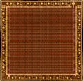
40010 GA Metal Layer
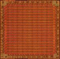
40010 GA with Metal Layer removed
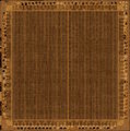
40226 PreASIC Metal Layer


See also
- Video modes : for other informations on colours and pixels.
- Synchronising with the CRTC and display : technical details on the relationship between Gate Array and CRTC.
- Media:40010-simplified V03.pdf Forum thread Gate Array schematics - reverse engineered by Gerald