Difference between revisions of "Dobbertin Smart Watch"
(→Technicals) |
(→Software) |
||
| Line 48: | Line 48: | ||
*Support for CP/M Plus is provided. The TIMEROM+.COM program sets the software clock according to the RTC. | *Support for CP/M Plus is provided. The TIMEROM+.COM program sets the software clock according to the RTC. | ||
*The Smart Watch is also supported by [[FutureOS]]. | *The Smart Watch is also supported by [[FutureOS]]. | ||
| + | |||
| + | ==Links== | ||
| + | *[http://www.cpcwiki.eu/forum/amstrad-cpc-hardware/dobbertin-smartwatch-help-needed-!/ CPCWiki Forum thread] | ||
[[Category:FutureOS]] | [[Category:FutureOS]] | ||
[[Category:Hardware]] | [[Category:Hardware]] | ||
[[Category:Peripherals]] | [[Category:Peripherals]] | ||
Revision as of 14:17, 15 March 2015
The Dobbertin Smart Watch was produced by Dobbertin Industrie Elektronik, a German company. This real time clock was relative wide spread in the 80ies and 90ies.
Contents
Technicals
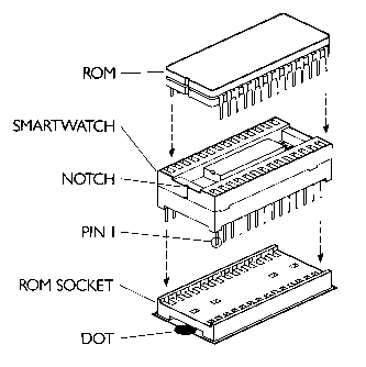
The SmartWatch consists out of the RTC itself and an EPROM expansion with a lot of RSX commends. The RTC itself was inserted like an EPROM in any kind of ROM or EPROM card. Further it contains a little battery. At least one clock is still running in 2014!
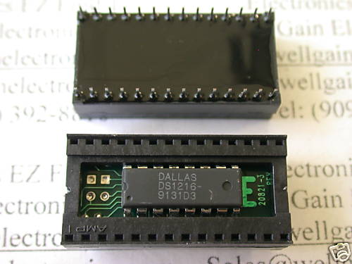
Dallas Semiconductors SmartWatch
The 28pin SmartWatch (DS1216) is an adapter that can inserted in standard ROM sockets, a ROM chip can be mounted on the adapter, finally, inside of the adapter is a 16pin Phantom Time Chip (DS1315). Normal memory reads are forwarded to the piggyback ROM. After reading from a specific sequence of addresses, the ROM is disabled, and data is instead read from the Phantom Chip via 1bit databus. Writing to the Phantom Chip is done by reading from a specific sequence of addresses, too.
- DS1216-smart-watch.pdf - Dallas Datasheet for 28pin SmartWatch Adapter
- DS1315-phantom-time-chip.pdf - Dallas Datasheet for 16pin Phantom Time Chip
- DS1216-app-note-52.pdf - Dallas Application Note on SmartWatch and Phantom Time Chip
64bit packets
Accessing the RTC is done by following steps
- Read 1 or more bits (this resets the recognition pattern; best read at least 64 bits, in case the chip was in the 64-bit data read phase)
- Write the 8-byte (64bit) recognition pattern
- Read or Write the 8-byte (64bit) register data
The 8-byte (64bit) pattern/data is transferred serially, LSB first. The used bits on address and databus are:
A2 data direction (0=write, 1=read)
A0 data written to RTC, when A2=0=write
D0 data read from RTC, when A2=1=read, and only when pattern recognized
Recognition Pattern
The recognition pattern is: C5h, 3Ah, A3h, 5Ch, C5h, 3Ah, A3h, 5Ch.
Register 0..7
0  1/100 Seconds (BCD 00h..99h)
1  Seconds       (BCD 00h..59h) (Bit7=Zero)
2  Minutes       (BCD 00h..59h) (Bit7=Zero)
3  Hours         (BCD 01h..12h or 00h..23h) (Bit5=PM when Bit7=12-hour mode) (Bit6=Zero)
4  Day of Week   (01h..07h) (Bit4=Disable Reset input, Bit5=Disable OSC, stop clock) (Bit3,6,7=Zero)
5  Day           (BCD 01h..31h) (Bit6-7=Zero)
6  Month         (BCD 01h..12h) (Bit5-7=Zero)
7  Year          (BCD 00h..99h)
Pictures
Downloads
- TIME ROM+ ROM file
- (disc with CP/M driver) - none such...?
Software
- The TimeROM+ Software provides RSX commands to use the RTC under BASIC.
- Support for CP/M Plus is provided. The TIMEROM+.COM program sets the software clock according to the RTC.
- The Smart Watch is also supported by FutureOS.

