Difference between revisions of "Atari-ST mouse adapter"
From CPCWiki - THE Amstrad CPC encyclopedia!
| Line 21: | Line 21: | ||
The circuit reportedly doesn't work on CPC Plus computers. | The circuit reportedly doesn't work on CPC Plus computers. | ||
The Atari-ST adapter is supported by G-Paint 2.0. | The Atari-ST adapter is supported by G-Paint 2.0. | ||
| + | |||
| + | [[Category:Hardware]] [[Category:Peripherals]] [[Category:DIY]] | ||
Revision as of 06:19, 8 January 2010
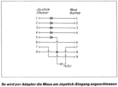
The schematic was released in german magazine "Schneider Magazin, 07/1988", apparently using 5 diodes and a 4.5V battery.
Aside from Atari-ST mice, the circuit should also work for Amiga mice, which are basically the same, but with XA/XB/YA/YB connected to other pins, which could be resolved at software side (or at hardware side).
 CPC Joy Port                     Atari-ST Mouse      Amiga Mouse
 JoyUp    Pin1 --|>|------------- Pin1 XB             Pin1 YA
 JoyDown  Pin2 --|>|------------- Pin2 XA             Pin2 XA
 JoyLeft  Pin3 --|>|------------- Pin3 YA             Pin3 YB
 JoyRight Pin4 --|>|------------- Pin4 YB             Pin4 XB
 JoyFire2 Pin6 ------------------ Pin6 Left Button    Pin6 Left Button
 JoyFire1 Pin7 ------------------ Pin9 Right Button   Pin9 Right Button
 JoyFire3 Pin5 --|>|------------- Pin8 GND            Pin8 GND
 JoySel1  Pin8 ------------------ Pin8 GND            Pin8 GND
 Batt4.5V (-)  ------------------ Pin8 GND            Pin8 GND
 Batt4.5V (+)  ------------------ Pin7 +5V            Pin7 +5V
The low-level XA/XB/YA/YB signal must be watched by software (the 300Hz interrupt is probably too slow to sense fast motions, so there's little chance to have the mouse driver running in background).
The circuit reportedly doesn't work on CPC Plus computers. The Atari-ST adapter is supported by G-Paint 2.0.
