Difference between revisions of "AMRAM2"
| Line 18: | Line 18: | ||
This came after the AMRAM which was 16K ram on a board which could be programmed and which occupied ROM slot 5. More details when I can find them in my documents. | This came after the AMRAM which was 16K ram on a board which could be programmed and which occupied ROM slot 5. More details when I can find them in my documents. | ||
| − | [[File: | + | [[File:Amram2_all.jpg]] |
[[File::Amram2_bare.jpg]] | [[File::Amram2_bare.jpg]] | ||
Revision as of 17:10, 31 October 2009
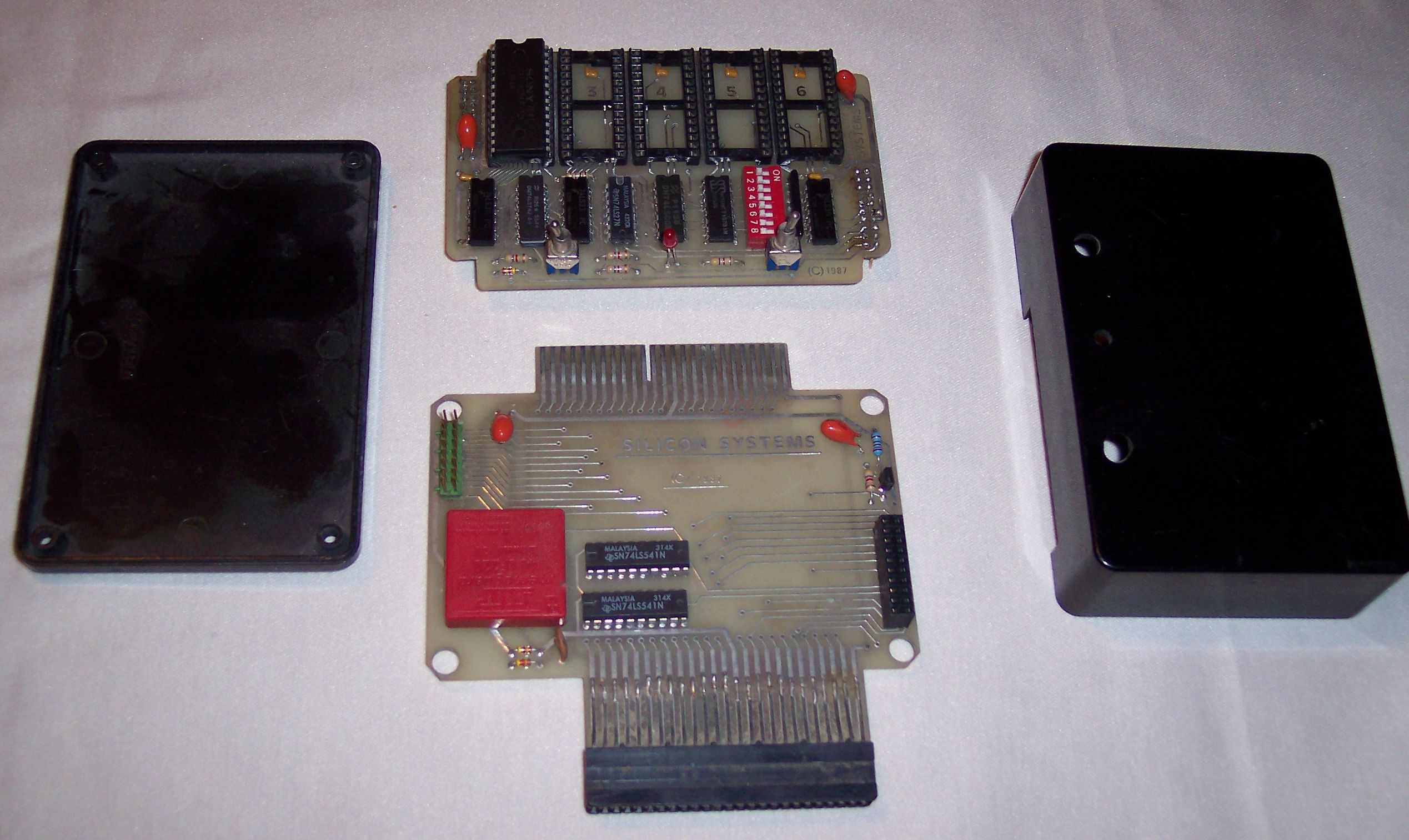
AMRAM2 is a ROM board from Silicon Systems.
The AMRAM has two PCBs sitting on top of each other, joined with a rigid connector.
On the bottom is passthrough for other expansion connectors and a 3V square lithium battery.
On the top, 32K RAM (contents are held by lithium battery so can survive a reset or power off), which can be programmed like ROM and occupies two ROM positions (1 and 2 I think). Also sockets for more ROMs up to max 7.
Also there is a bank of DIP switches to enable/disable ROM slots, a switch to enable/disable writes to 32K RAM, a LED to indicate RAM is ready to write and a switch to reset computer.
It seems the first few batches of these were distributed without boxes, so you had to provide your own, because the box I have with mine is home made.
I/O ports for enabling RAM - not know yet. Will add when I find them out.
Came with software to program it.
This came after the AMRAM which was 16K ram on a board which could be programmed and which occupied ROM slot 5. More details when I can find them in my documents.
[[File::Amram2_bare.jpg]]
[[File::Amram2_base_pcb2.jpg]]
[[File::Amram2_base_pcb.jpg]]
[[File::Amram2_top_pcb2.jpg]]
