Installing Vortex Expansion RAM
Below are installation notes for the Vortex Expansions RAM card from Kevin Thacker. Note: Further info (in german) can be found in the official Vortex SP 512 kb RAM Expasion Manual (pdf).
SP512 RAM expansion
The SP512 is a 512K RAM expansion which came in versions for the CPC 464 and the CPC 664 made by Vortex GmbH and are fitted inside the CPC casing.
There are 3 connections to the main CPC464 P.C.B.
- One connection to the socket where the Z80 CPU is sited,
- One connection to the socket where the Gate Array (40007/40010) is sited,
- One connection point to a resistor on the main P.C.B,
The SP512 can't be fitted to:
- Cost-down revision of the CPC464.
- Reason: The Gate-Array is of a different design and is soldered to the main P.C.B.
- CPC6128.
- Reason: The Gate-Array and Z80 CPU sit in positions which the SP512 can't connect to.
- 464+ or 6128+.
- Reason: These two use a new design with an ASIC which is soldered to the main P.C.B. The SP512 can't connect to this.
It is not worth the effort trying to connect the SP512 to the above computers when there are alternative RAM expansions available.
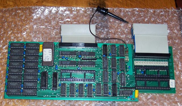
Image showing top of SP512 RAM expansion P.C.B.:
In the middle is the socket for the Z80 CPU. Above that socket is the cable and connector which connect to the site of the Z80 CPU on the main P.C.B. To the right are two sockets for different versions of the Gate-Array. Above those sockets is the cable and connector which connect to the site of the Gate-Array on the main P.C.B. Notice the three positions that the lead can be put into. In this picture, the lead is in position 2. Position 1 is obscured by the lead.
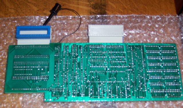
Image showing bottom of SP512 RAM expansion P.C.B.:
The SP512 has an on-board 16K EPROM which contains B.O.S (Banked Operating System) which is assigned to ROM position 6. This assignment is fixed and the ROM can't be disabled, so if you want to use a ROM board ensure position 6 is not used.
When the computer is turned on the message "BOS 2.1 SP512 (C)1987 vortex GmbH" is displayed followed by a short pause. RSX commands are now available. (Technical Note: B.O.S hooks into 'KL FIND COMMAND' to provide it's commands instead of using the recommended 'KL LOG EXT').
Fitting the SP512
- Turn the CPC464 over and remove the screws
- Turn the CPC464 over and lift the top from the base. There are two connections from the top to the base. One for the keyboard and one for the cassette sub P.C.B. Remove both of these.
- Ensure you have touched something metal to remove static electricity from your body. Touching a water pipe or the pipe into a radiator often does the job.
- Carefully remove the Z80 CPU from it's socket. Put it to one side.
- Carefully remove the Gate-Array from it's socket.
- There are two versions of the Gate-Array, '40007' and '40010'. These may be marked on the P.C.B. Otherwise this is how you can identify them:
- 40007: This version of the Gate-Array often has a flat piece of metal stuck to the top of it it with white paste. There is another piece of metal which holds it in place and this goes under the Gate-Array itself.
- 40010: This version of the Gate-Array can be identified from the markings.
- For the '40007', carefully remove both the Gate-Array and both pieces of metal together. Do not seperate.
- For the '40010', use an I.C. lifting tool or follow the tip below.
- Tip for removing ICs:
- You can remove ICs using a flat head screwdriver. Put the head of the screw driver under the IC at one end of the socket and lever it up gently. Do the same on the other side. Repeat on both sides until the I.C. can be removed from the socket. Be careful not to break any it's feet. If any feet have bent, then carefully straigten them back into position. If any feet have broken then you have to find a replacement IC.
- There are two versions of the Gate-Array, '40007' and '40010'. These may be marked on the P.C.B. Otherwise this is how you can identify them:
- Lay the SP512 P.C.B. flat on a table with a piece of packing material underneath.
- Fit the Z80 into the socket on the SP512 P.C.B, align the notch on the Z80 with the notch on the socket. Press firmly into position.
- Fit the Gate-Array into the appropiate socket on the SP512 P.C.B, align the notch on the Gate-Array with the notch on the socket. Press firmly into position.
- NOTE: There are two sockets that the Gate-Array can fit into.
- The top socket is for the 40007 version of the Gate-Array.
- The bottom socket is for the 40010 version of the Gate-Array.
- Either of these may be fitted to your CPC464 and with some P.C.B. designs there is often space for both. My CPC464 had a 40010 type.
- NOTE: There are two sockets that the Gate-Array can fit into.
- The SP512 has three positions for the connection from the SP512 to the CPC464 P.C.B. The SP512 has been designed so that it can be used with various revisions of the CPC464 P.C.B. I had to adjust this to connect the SP512 to my CPC464.
- To find the appropiate position:
- Hold the SP512 P.C.B. above the CPC464 P.C.B, align the connector for the Z80 CPU so it is over the socket for the Z80 on the CPC464 P.C.B.
- Make a note of the position of the Gate-Array socket on the CPC464 P.C.B.
- Adjust the connector so that it is over the socket for the Gate-Array on the CPC464 P.C.B.
- To find the appropiate position:
- Connect the SP512 to the CPC464 P.C.B. press the connector for the Z80 and the Gate-Array firmly into position.
- Hook the end of the lead from the SP512 onto the top of resistor R112 on the CPC464 P.C.B..
- On some CPCs there is a rubber or foam block stuck to the bottom of the main P.C.B. You may need to cut this so that the SP512 P.C.B. will be almost horizontal and so that the two pieces of the CPC464 can close together. This can be cut with a pair of scissors. You can put the old piece of the foam/rubber onto the top of the SP512 so that it can be used to stop the underneath of the keyboard from touching the SP512 P.C.B.
- Connect the leads between the top of the CPC464 keyboard with the bottom (one for keyboard, one for cassette).
- Close the two pieces of the CPC464 together.
- Turn it over and fit the screws.
- Connect power lead to computer and switch it on.
Removal of the SP512
Removal of the SP512 is almost the reverse of fitting.
- Turn the CPC464 over and remove the screws.
- Turn the CPC464 over and lift the top from the base. One for the keyboard and one for the cassette sub P.C.B. Remove both of these.
- Ensure you have touched something metal to remove static electricity from your body. Touching a water pipe or the pipe into a radiator often does the job.
- Carefully disconnect the SP512 from the CPC464 P.C.B. There are three connections.
- Lay the SP512 P.C.B. flat on a table with a piece of packing material underneath.
- Carefully remove the Z80 CPU from the SP512.
- Put the Z80 into the socket marked 'IC111' on the CPC464 P.C.B. aligning the notch on the Z80 with the notch in the socket. Press firmly into position.
- Carefully remove the Gate-Array from the SP512:
- There are two versions of the Gate-Array. One is marked '40010', the other has a flat piece of metal stuck to the top of it with white paste, this is the '40007' type. For the 40007, remove both the IC and the metal together. Do not seperate.
- Put the Gate-Array into the socket marked 'IC116' on the CPC464 P.C.B. aligning the notch on the Gate-Array with the notch in the socket. Press firmly into position. The position of the Gate-Array may be identified on the P.C.B.
- Connect the leads between the top of the CPC464 keyboard with the bottom (one for keyboard, one for cassette).
- Close the two pieces of the CPC464 together.
- Turn it over and fit the screws.
- Connect power lead to computer and switch it on.
SP512 RAM expansion - before and after fitting
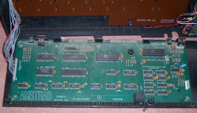
This image shows the CPC464 main P.C.B. before the RAM expansion is fitted. From this picture you can see the original locations of the Z80 CPU and the Gate-Array:
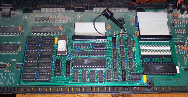
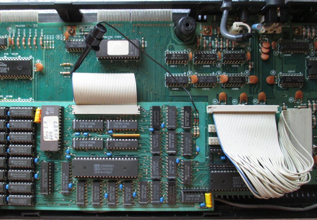
This image shows the CPC464 main P.C.B. after the RAM expansion is fitted. Notice the P.C.B. of the RAM expansion, the new location of the Z80 CPU and Gate-Array:
This image shows how the CPC 664 version is mounted inside the CPC casing:
