A surgical guide to the Amstrad NC
Contents
- 1 A Surgical Guide To The Amstrad Notepad Computer
- 2 IC Pinouts
- 2.1 The Microprocessor (MPU, IC301)
- 2.2 The Custom Chip (IC302)
- 2.3 The Firmware EPROM (IC303)
- 2.4 The Static Random Access Memory (SRAM, IC304 and IC305)
- 2.5 The PCMCIA card slot (IC306)
- 2.6 The Real-Time-Clock (RTC, IC307)
- 2.7 The Universal Asynchronous Receiver Transmitter (UART, IC308)
- 2.8 The RS232-Driver (IC309)
- 2.9 The RS232-connector pinout
A Surgical Guide To The Amstrad Notepad Computer
This page is based on Hans-Jürgen Böhling's "surgical guide to the Amstrad NC". The original document is avaliabe here [1] (author's website) or here Media:sg-nc100.zip (local copy)
Amstrad Notepad Computer - What is it?
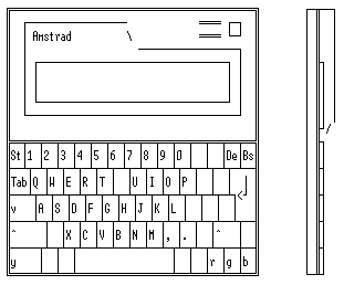
The model NC100 is about DIN A4 size with a LCD 8 lines * 80 characters screen, nearly full size keyboard, a PCMCIA memory card slot on the right hand side and four coloured keys. The Notepads have standard Centronics parallel port (DB-25 pin famale connector) and RS232 (DB 9 pin male) serial port. The system has drivers for 9 and 24 pin dot matrix, Canon inkjet and Laserjet printers. The serial connector support 300, 1200, 2400, 4800, or 9600 bps. As power supply the NC100 use 4 * AA sice batteries or an AC adapter. As backup battery ther is also a CR2032 3 Volt lithium cell.
The model NC150 (it seems) is retailing only in Italy and Fance. It has 512K bytes firmware ROM and 128K RAM. The extra 256K bytes ROM contains a spreadsheet and the arcade game 'BLOCKADE' (similar to TETRIS).
The model NC200 include the additional features of the NC150 but also a 720K MS-DOS compatible 3.5 inch floppy disk drive and a 16 lines by 80 characters screen witch had to be fold up like a laptop.
Specifications
Model                : NC100
Processor            : Z80 compatible CMOS
Operating
frequency            : 4.606 MHz
Memory               : 64K byte internal
                       (15K system-, 11K upper-, 38K lower memory)
Storage              : PCMCIA/JEIDA Memory Cards (PC-Cards) Type I
                       max. 1M byte SRAM 5 Volt
Display              : 480*64 pixel display (usually 80*8 characters)
Weight               : 930 g
Height               :  22 mm
Width                : 295 mm
Length               : 210 mm
Power Consumption ON : 40 - 60 mA
Built in firmware    : 256K byte with

        - Texteditor with mailmerge and spellchecker
        - Address book
        - Time manager (diary with alarm-clock)
        - Calculator
        - Terminal-programm (serial Tranfer with ASCII or XModem)
        - BBC-BASIC with Assembler support
How to get the Firmware Number?
When you are in the main Menu (text editor, calculater, calender) push the secret-button and the system-settings menu appears, the version number will be shown in the first line of the sceen. I have a german NC100 and the firmware number is v1.06.
PCMCIA Memory Cards
A battery buffered PCMCIA SRAM-Memory Card will preserve you from data loss even if your Notepad crashes and increases the available memory. It also allows you to create a file with BBC-BASIC bigger than 1024 bytes. This is because BBC-BASIC allocates all available memory on startup except 1024 bytes. The maximum size to use with the NC100 is up to 1M byte.
How to open the NC100?
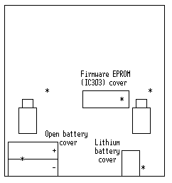
Before disassembling the Notepad you should save all your data! Then put the Notepad on the table face down. Remove the four AA size batteries, then unscrew the five screws (one under the battery cover). In the drawing below they are marked with a "*"-sign. One screw fixes the cover of the firmware EPROM.Place the Notepad the right way up and lift off the upper part of the case. Be careful, because the display is still connected to the main-board via a folio-flat-cable and so is the speaker! Don't be nervous, the cables can be simply pulled out of their sockets. Now you can separate the covers.
What is inside?
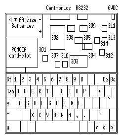
Inside the NC100 is a SMD layout. I have a german NC100 and the circuit board is labeled Amstrad plc 4500-001P-1, NA999-32142, manual marked C (A-H) and 1 (1-8). All IC's are SMD apart from IC303 which is on the backside of the NC100 (behind the firmware EPROM cover). On the drawing below I have labeled all ICs, but you can find it on the layout also!
The table below gives a description of the IC's in the NC100:
╔════Ð═══════════════Ð════════Ð═══════════════════════════════════════╗ ║IC-#│Label │Pin's │Description ║ Ã────┼───────────────┼────────┼─────────────────────────────────────── ║301 │ZILOG │4*11= 44│Z84C00 ║ ║ │Z84C0006FEC │PLCC 44 │CMOS, 6 MHz ║ ║ │Z80 CPU │ │Z80 compatible Microprocessor ║ Ã────┼───────────────┼────────┼─────────────────────────────────────── ║302 │NEC Japan │4*34=136│µPD 65034 ║ ║ │D65034GD093 │PLCC 136│Custom ASIC ║ Ã────┼───────────────┼────────┼─────────────────────────────────────── ║303 │NEC Japan │2*16= 32│27C2001 = CMOS EPROM 256K*8 bit ║ ║ │D27C2001 │DIL 32 │Firmware EPROM ║ Ã────┼───────────────┼────────┼─────────────────────────────────────── ║304 │NEC JAPAN │2*14= 28│µPD 43257 A = CMOS SRAM 32K*8 bit ║ ║ │D43257AGU-10LL │SO 28 │Memory layouted as an SO 32 (32 pin)! ║ Ã────┼───────────────┼────────┼─────────────────────────────────────── ║305 │NEC Japan │2*14= 28│µPD 43257 A = CMOS SRAM 32K*8 bit ║ ║ │D43257AGU-10LL │SO 28 │Memory ║ Ã────┼───────────────┼────────┼─────────────────────────────────────── ║306 │MEMORY CARD │2*34= 68│PCMCIA/JEIDA Memory Cards Slot Type I ║ ║ │ │PCMCIA │for max. 1M byte SRAM Memory, 5 Volt ║ Ã────┼───────────────┼────────┼─────────────────────────────────────── ║307 │T 9224 HB │2*10= 20│TC8521 ║ ║ │ 8521 AM │SO 20 │Real-Time-Clock ║ Ã────┼───────────────┼────────┼─────────────────────────────────────── ║308 │NEC Japan │2*14= 28│µPD 71051 ║ ║ │D71051 GU │SO 28 │UART (parallel to seriell transpose) ║ Ã────┼───────────────┼────────┼─────────────────────────────────────── ║309 │NEC Japan │2*10= 20│µPD 4711 ║ ║ │D4711 AG │SO 20 │RS232-driver (shift level to +/- 10V) ║ Ã────┼───────────────┼────────┼─────────────────────────────────────── ║310 │not placed │2* 7= 14│74HC00 = CMOS-Logic 4 * NAND ║ ║ │ │SO 14 │(only used if IC304/IC305 = 43256) ║ Ã────┼───────────────┼────────┼─────────────────────────────────────── ║311 │D4584G │2* 7= 14│4584 = CMOS-Logic 6 * Schmitt-Trigger ║ ║ │ │SO 14 │ ║ Ã────┼───────────────┼────────┼─────────────────────────────────────── ║312 │C339 G │2* 7= 14│LM339 = 4 * Comparator ║ ║ │ │SO 14 │(used for battery level detection) ║ Ã────┼───────────────┼────────┼─────────────────────────────────────── ║313 │D4013G │2* 7= 14│4013 = CMOS-Logic 2 * D-Flip Flop ║ ║ │ │SO 14 │with set and reset ║ Ã────┼───────────────┼────────┼─────────────────────────────────────── ║314 │D4584G │2* 7= 14│4584 = CMOS-Logic 6 * Schmitt-Trigger ║ ║ │ │SO 14 │ ║ ╚════¤═══════════════¤════════¤═══════════════════════════════════════╝
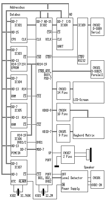
Amstrad NC100/NC150 Simplfied Bock Diagram
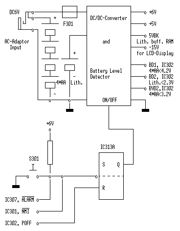
Amstrad NC100/150 Power Supply Bock Diagram
IC Pinouts
On the next pages folowing the pinouts off the most important ICs used in the NC100. '*' indicates active Low and 'NC' is Not Connected in the NC100
The Microprocessor (MPU, IC301)
Type                         : Z84C00
Manufacturer                 : Zilog Inc.
Description                  : Microprocessor, 8-Bit
Power Consumption            : 15 mA typ. at 6 MHz
Process                      : CMOS
Supply Voltage               : +5V
Operating frequency max.     : 6 MHz
Package                      : PLCC 44 pin

Features :

 - Commands compatible with Zilog Z80 MPU
 - Powerful set of 158 instructions including the 78 of the 8080A
 - 10 addressing modes
 - Power down mode when the system clock is stopped

Pinout :

1        A11                23       *RD
2        A12                24       NC
3        A13                25       NC
4        A14                26       *WR
5        A15                27       *BUSACK
6        NC                 28       *WAIT
7        CLK                29       *BUSREQ
8        D4                 30       *RESET
9        D3                 31       *M1
10       D5                 32       *RFSH
11       D6                 33       GND
12       NC                 34       A0
13       VCC                35       A1
14       D2                 36       A2
15       D7                 37       A3
16       D0                 38       A4
17       D1                 39       A5
18       *INT               40       A6
19       *NMI               41       A7
20       *HALT              42       A8
21       *MREQ              43       A9
22       *IORQ              44       A10
The Custom Chip (IC302)
Type                         : µPD 65034
Manufacturer                 : NEC Electronics
Description                  : Custom Chip with multiple funktions
Process                      : CMOS
Supply Voltage               : +5V
Package                      : PLCC 136

The chip has multiple functions:

- Clock generator for CPU and UART
- Peripher Interface Adaptor (to printer, LCD-screen, keybord,)
- Memory Management Unit
- PCMCIA-Interface
- Sound generator for speaker

Pinout :

1     VDD          35    GND          69    VDD          103   GND
2     KBI1         36    GND          70    TEMP         104   GND
3     KBI5         37    AO18         71    UCLK         105   *STRB
4     KBI7         38    AO19         72    RRDY         106   *CD2
5     KBI6         39    GND          73    TRDY         107   *CD1
6     KBI4         40    CLK          74    *STBY        108   *CE1
7     KBI3         41    HALT         75    LD0          109   *OE1
8     KBI2         42    *MREQ        76    LD1          110   *WE1
9     KBI0         43    *IORQ        77    LD2          111   *REG
10    A0           44    *BACK        78    LD3          112   BVD2
11    A1           45    *BREQ        79    FRM          113   BVD1
12    A2           46    *WAT         80    DF           114   WP
13    A3           47    *M1          81    LOAD         115   MD3
14    A4           48    *INT         82    CP           116   MD4
15    A5           49    *RD          83    POFF         117   MD5
16    A6           50    *WR          84    SP           118   GND
17    GND          51    DO           85    GND          119   MD6
18    GND          52    D1           86    GND          120   MD7
19    A7           53    D2           87    BD1          121   MD0
20    A8           54    D3           88    BD2          122   MD1
21    A9           55    GND          89    *NMIC        123   MD2
22    A10          56    D4           90    *RES         124   TEST (NC)
23    A11          57    D5           91    URES         125   KBO9
24    A12          58    D6           92    *BUSY        126   KBO8
25    A13          59    D7           93    *ACK         127   KBO7
26    A14          60    RRD          94    PD7          128   KBO6
27    A15          61    *CS0         95    PD6          129   KBO1
28    AO14         62    *CS1         96    PD5          130   KBO2
29    AO15         63    *CS2         97    PD4          131   KBO5
30    AO16         64    *CS3         98    PD3          132   KBO4
31    AO17         65    *CS4         99    PD2          133   KBO3
32    X2           66    TRXC         100   PD1          134   KBO0
33    X1           67    GND          101   PD0          135   GND
34    VDD          68    GND          102   VDD          136   GND
The Firmware EPROM (IC303)
Type                         : µPD 27C2001
Manufacturer                 : NEC Electronics
Description                  : EPROM, 2Mb, 8-Bit, UV-eraseable
Org.                         : 256K x 8 Bit
Process                      : CMOS
Supply Voltage               : +5V
Standby                      : 0.5 mW
Operation                    : 150 mW
Package                      : DIL

Pinout :

1         NC  (A19)         17          O3
2         A16               18          O4
3         A15               19          O5
4         A12               20          O6
5         A7                21          O7
6         A6                22          *CE
7         A5                23          A10
8         A4                24          *OE
9         A3                25          A11
10        A2                26          A9
11        A1                27          A8
12        A0                28          A13
13        O0                29          A14
14        O1                30          A17
15        O2                31          NC  (A18)
16        GND               32          VCC


The NC100 can also control  27C4001 (512K), 23C2001 (256K), 23C4001 (512K),
23C8001  (1M byte) EPROM's!  By  the  type of the EPROM there had to be set
some  different  connections,  this  connections  are  set  by zero Ohm
SMD-resistors from the backside of the board close to IC303:

             ╔═════════Ð════════Ð══════Ð══════Ð══════Ð══════╗
             ║  IC303  │ Kbyte  │ J301 │ J302 │ J303 │ J304 ║
             ╠═════════Ï════════Ï══════Ï══════Ï══════Ï══════╣
             ║ 27C2001 │  256   │      │      │  +   │  +   ║
             Ã─────────┼────────┼──────┼──────┼──────┼──────Â
             ║ 27C4001 │  512   │   +  │      │  +   │      ║
             ╠═════════Ï════════Ï══════Ï══════Ï══════Ï══════╣
             ║ 23C2001 │  256   │      │      │  +   │  +   ║
             Ã─────────┼────────┼──────┼──────┼──────┼──────Â
             ║ 23C4001 │  512   │      │  +   │      │  +   ║
             Ã─────────┼────────┼──────┼──────┼──────┼──────Â
             ║ 23C8001 │ 1024   │  +   │  +   │      │      ║
             ╚═════════¤════════¤══════¤══════¤══════¤══════╝

                                  + = use

I have double my ROM-space by set in a 27C4001 EPROM, remove J304 and set
in J301 by a pice of wire.
The Static Random Access Memory (SRAM, IC304 and IC305)
Type                         : µPD 43257A
Manufacturer                 : NEC Electronics
Description                  : SRAM, 256K Bit
Org.                         : 32K x 8 Bit
Process                      : CMOS
Supply Voltage               : +5VBK (Lithium battery buffered)
Standby                      : 0.5 mW
Operation                    : 225 mW
Package                      : SO 28

Pinout :

1         A14               15          DQ4
2         A12               16          DQ5
3         A7                17          DQ6
4         A6                18          DQ7
5         A5                19          DQ8
6         A4                20          *CS
7         A3                21          A10
8         A2                22          *OE
9         A1                23          A11
10        A0                24          A9
11        DQ1               25          A8
12        DQ2               26          A13
13        DQ3               27          *WE
14        GND               28          VCC


On my NC100 the IC304 is layouted as an SO 32 (32 pin). I  belief  you  can
put some bigger RAM-chip in the circuit, but there is nothing about that in
the  electronic  diagram!  There is only that the NC100 can control a 43256
RAM-chips. By the type of the RAM-chip there had to be set  some  different
connections and use IC310:

            ╔═══════════Ð══════Ð══════Ð══════Ð══════Ð═══════╗
            ║IC304, 305 │ J305 │ J306 │ J307 │ J308 │ IC310 ║
            ╠═══════════Ï══════Ï══════Ï══════Ï══════Ï═══════╣
            ║43256      │  +   │      │      │      │   +   ║
            Ã───────────┼──────┼──────┼──────┼──────┼───────Â
            ║43257      │      │  +   │  +   │  +   │       ║
            ╚═══════════¤══════¤══════¤══════¤══════¤═══════╝

                                  + = use
The PCMCIA card slot (IC306)
The NC-100 can use PCMCIA/JEIDA Memory Cards (PC-Cards) Type I, max. 1024K (1M) byte static ram card, 5 Volts. You can bye them in 64Kb, 128Kb, 256Kb, 512Kb, and 1024Kb sizes. The flash memory cards are not suitable for the NC-100. These have a control register that must be written to before any read or write can take place. Data transfers are then be done in sector chunks.
PCMCIA Card Connector Type I, 5 Volts:

            1 mm                                        1 mm
             ││                                          ││
             ││   34                                1    ││
             ┌───────────────────────────────────────────┐│────────────
   1.6 mm ───└┐    ■■■■■■■■■■■■■■■■■■■■■■■■■■■■■■■■■■    ││       3.4 mm
          ───┌┘    ■■■■■■■■■■■■■■■■■■■■■■■■■■■■■■■■■■    └┐─── 1 mm
             └────────────────────────────────────────────┘────────────
             │    68                                35    │
             │                   54 mm                    │


PCMCIA Version 2.0 Pinout:

 1       GND                       35       GND
 2       D3       I/O              36       *CD1     O
 3       D4       I/O              37       D11      I/O  (NC)
 4       D5       I/O              38       D12      I/O  (NC)
 5       D6       I/O              39       D13      I/O  (NC)
 6       D7       I/O              40       D14      I/O  (NC)
 7       *CE1     I                41       D15      I/O  (NC)
 8       A10      I                42       *CE2     I    (NC)
 9       *OE      I                43       RFSH     I    (NC)
10       A11      I                44       RFU      I    (NC)
11       A9       I                45       RFU      I    (NC)
12       A8       I                46       A17      I
13       A13      I                47       A18      I
14       A14      I                48       A19      I
15       *WE/PGM  I                49       A20      I    (NC)
16       RDY/*BSY O                50       A21      I    (NC)
17       VCC                       51       VCC
18       VPP1                      52       VPP2
19       A16      I                53       A22      I    (NC)
20       A15      I                54       A23      I    (NC)
21       A12      I                55       A24      I    (NC)
22       A7       I                56       A25      I    (NC)
23       A6       I                57       RFU           (NC)
24       A5       I                58       RESET    I    (NC)
25       A4       I                59       *WAIT    O    (NC)
26       A3       I                60       RFU           (NC)
27       A2       I                61       *REG     I
28       A1       I                62       BVD2     O
29       A0       I                63       BVD1     O
30       D0       I/O              64       D8       I/O  (NC)
31       D1       I/O              65       D9       I/O  (NC)
32       D2       I/O              66       D10      I/O  (NC)
33       WP       O                67       *CD2     O
34       GND                       68       GND
                 RFU  = Reserved Future Use
The Real-Time-Clock (RTC, IC307)
Type                         : TC8521AP/AM
Manufacturer                 : Toshiba Corporation
Description                  : Real Time Clock
Process                      : CMOS
Supply Voltage               : +5VBK (Lithium battery buffered)
Power Dissipat. max          : 1.25 mW
Package                      : SO 20

Features :

 - Clock funktion (hr, min, sec, date, day of week, year and leap year)
   auto-calendar
 - Clock system of 24-hour or 12-hour selectable
 - +/- 30 sec correction funktion
 - Alarm signal or pulse of 16Hz or 1Hz can be output
 - Built-in 26*4 bit RAM
 - 4-bit bidirectional data bus
 - 4-bit address input
 - Directly connectable with CPU bus
 - Capable of battery backup


Pinout :

1        *CS
2        CS
3        ADJ
4        A0
5        A1
6        A2
7        NC
8        A3
9        *RD
10       GND
11       *WR
12       D0
13       D1
14       D2
15       D3
16       *ALARM
17       NC
18       XIN
19       XOUT
20       VCC
The Universal Asynchronous Receiver Transmitter (UART, IC308)
Type                         : µPD 71051
Manufacturer                 : NEC Electronics
Description                  : UART Serial Control Unit
Process                      : CMOS
Supply Voltage               : +5V
Package                      : SO 28

Features :

 - Synchronous and asynchronous operation
 - Full duplex, double buffered transmitter / receiver
 - Error detektion at parity, overrun and framing
 - 5 to 8 bit characters
 - Low power standby mode
 - Functionally equivalant to the 8251A UART

Pinout :

1        D2
2        D3
3        RxDA TA
4        GND
5        D4
6        D5
7        D6
8        D7
9        *TxCLK
10       *WR
11       *CS
12       C/*D
13       *RD
14       RxRDY
15       TxRDY
16       SYNCBRK    (NC)
17       *CTS
18       TxE MP
19       TxDA TA
20       CLK
21       RES ET
22       *DSR       (NC)
23       *RTS
24       *DTR       (NC)
25       *RxCLK
26       Vdd
27       D0
28       D1
The RS232-Driver (IC309)
Type                         : µPD 4711A
Manufacturer                 : NEC Electronics
Description                  : RS232-Driver
Process                      : MOS-IC
Supply Voltage               : +5V
Power Dissipat.              : 60 mA
Package                      : SO 20

The  RS232-driver  shift  up  the  TTL-level  (0V/+5V)  output from UART to
RS232-level (+10V/-10V).

Pinout :

1        Vdd
2        C1+
3        Vcc
4        C1-
5        STB
6        Din1
7        Din2
8        Rout  1
9        Rout  2
10       GND
11       Rcon
12       Rin2
13       Rin1
14       Dout  2
15       Dout1
16       Dcon
17       Vss
18       C4-
19       GND
20       C4+
The RS232-connector pinout
(DTR just duplicates RTS)
Pin I/O Description
5       GND  Signal Ground
9   <─  RI   Ring Indicator (NC)
4   ─>  DTR  Data Terminal Ready
8   <─  CTS  Clear To Send
3   ─>  TD   Transmit Data
7   ─>  RTS  Request To Send
2   <─  RD   Receive Data
6   <─  DSR  Data Set Ready (NC)
1   <─  CD   Carrier Detect (NC)
Author:
Hans-Jürgen Böhling
Bülowstr. 2
40476 Düsseldorf
Germany

e-mail  : 101.107378@germanynet.de
homepage: http://www.germany.net/teilnehmer/101.107378/index.htm
