Difference between revisions of "AcidInside"
| Line 30: | Line 30: | ||
[[Image:AcidInside4.png|600px|centre]] | [[Image:AcidInside4.png|600px|centre]] | ||
| + | |||
| + | If you prefer to make this expansion using a vero board or even just directly wiring the IC Socket to the riser PCB, then these are the connections that need to be made: | ||
| + | |||
| + | {|{{Prettytable|width: 700px; font-size: 2em;}} | ||
| + | |''ACID Pin''||''Cartridge Pin'' | ||
| + | |- | ||
| + | |1||B1, A1, A2 | ||
| + | |- | ||
| + | |2||B13 | ||
| + | |- | ||
| + | |3||B17 | ||
| + | |- | ||
| + | |4||NC | ||
| + | |- | ||
| + | |5||B2 | ||
| + | |- | ||
| + | |6||A3 | ||
| + | |- | ||
| + | |7||B8 | ||
| + | |- | ||
| + | |8||B1, A1, A2 | ||
| + | |- | ||
| + | |9||A7 | ||
| + | |- | ||
| + | |10||A8 | ||
| + | |- | ||
| + | |11||A9 | ||
| + | |- | ||
| + | |12||A10 | ||
| + | |- | ||
| + | |13||B10 | ||
| + | |- | ||
| + | |14||B11 | ||
| + | |- | ||
| + | |15||B12 | ||
| + | |- | ||
| + | |16||A18, B18 | ||
| + | |- | ||
| + | |} | ||
| + | |||
| + | The 100nf capacitor should be soldered between pins 1 and 16 of the ACID socket. | ||
Latest revision as of 08:43, 22 January 2012
Description
This modification makes it possible to have an internal ACID in your CPC+. This means that the CPC+ will run with ACIDless cartridges, homemade cartridges or cartridges where the ACID has been damaged.
Warning / Disclaimer
Although I have taken the utmost care preparing this documentation, I do not guarantee that it is error free and I accept no responsibility for damage to anyone’s hardware or other personal equipment or injury inflicted on you or others.
Construction
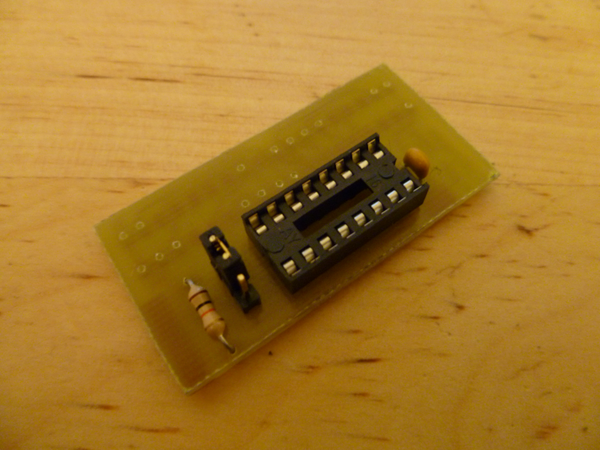
To make this device you'll obviously need to remove a good ACID from a working original cartridge. There's not a lot to say about the circuit. It simply connects the ACID to the correct pins for the ASIC to communicate properly with it. The jumper and 10K resistor were added to allow the user to disable the ACID if needed, but the CPC doesn't seem to have a problem with having two ACIDs in parallel, so there are no known situations where you would need this and you can simply leave out the 10K resistor and solder a simple bridge (ACID pin 7 to cartridge socket) instead of the jumper pins. The smoothing capacitor should be a 100nf ceramic capacitor.
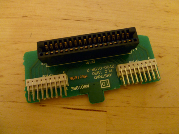
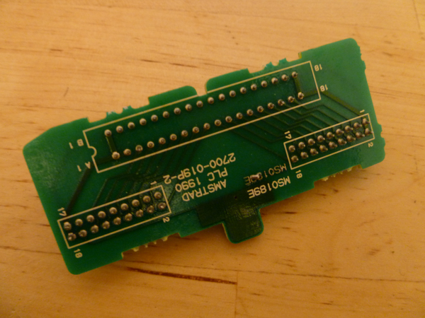
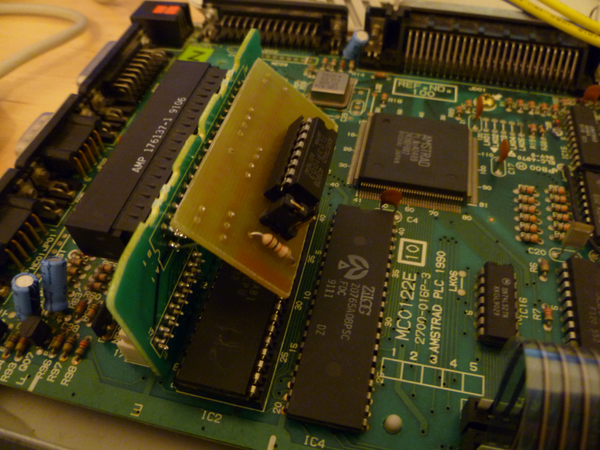
The circuit is soldered to the rear side of the cartridge riser PCB seen here. This can be unplugged to safely and more easily mount the new PCB. Luckily not all cartridge socket pins need to be soldered as it is quite awkward to solder. The new PCB needs to be soldered on at a slight angle so that it doesn't make contact with the Z80.
When all pins have been soldered it should look something like the picture below. The ACID can now be inserted and tested (with the cartridge that you took the ACID from perhaps). There is enough room inside the CPC to easily accomodate the PCB, so no modifications to the CPCs case are required.
If you prefer to make this expansion using a vero board or even just directly wiring the IC Socket to the riser PCB, then these are the connections that need to be made:
| ACID Pin | Cartridge Pin |
| 1 | B1, A1, A2 |
| 2 | B13 |
| 3 | B17 |
| 4 | NC |
| 5 | B2 |
| 6 | A3 |
| 7 | B8 |
| 8 | B1, A1, A2 |
| 9 | A7 |
| 10 | A8 |
| 11 | A9 |
| 12 | A10 |
| 13 | B10 |
| 14 | B11 |
| 15 | B12 |
| 16 | A18, B18 |
The 100nf capacitor should be soldered between pins 1 and 16 of the ACID socket.
Resources
This is the PCB layout for this modification:
Bryce.


