Difference between revisions of "DualOS"
(→Construction) |
|||
| (2 intermediate revisions by the same user not shown) | |||
| Line 2: | Line 2: | ||
| − | This modification will allow you to have two DOSs in a CPC6128 without the need of an | + | This modification will allow you to have two DOSs in a CPC6128 without the need of an additional PCB. By replacing the standard 16K EPROM with a 32K and switching the MSB (A14), you can choose the DOS that the CPC uses. |
| + | If you don't like making changes inside your CPC, then check out the [[LowerROM|LowerROM Board]] external solution. | ||
== Warning / Disclaimer == | == Warning / Disclaimer == | ||
| Line 46: | Line 47: | ||
| − | The EPROM should be burnt with whatever two OSs you wish to have, the first OS is saved from &0000 to &3FFF and the second OS should be located | + | The EPROM should be burnt with whatever two OSs you wish to have, the first OS is saved from &0000 to &3FFF and the second OS should be located at &4000 to &7FFF. |
The ROM image below is a single 32K file with AMSDOS and ParaDOS. | The ROM image below is a single 32K file with AMSDOS and ParaDOS. | ||
Latest revision as of 15:37, 5 November 2012
Description
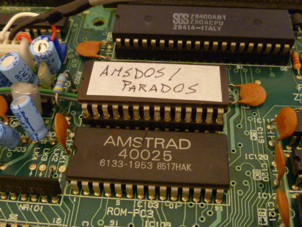
This modification will allow you to have two DOSs in a CPC6128 without the need of an additional PCB. By replacing the standard 16K EPROM with a 32K and switching the MSB (A14), you can choose the DOS that the CPC uses.
If you don't like making changes inside your CPC, then check out the LowerROM Board external solution.
Warning / Disclaimer
Although I have taken the utmost care preparing this documentation, I do not guarantee that it is error free and I accept no responsibility for damage to anyone’s hardware or other personal equipment or injury inflicted on you or others.
Construction
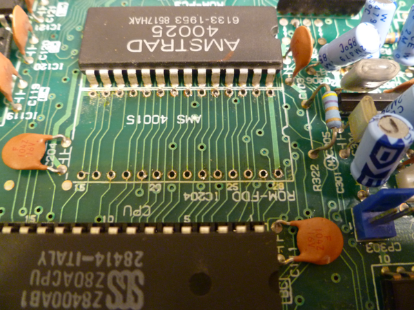
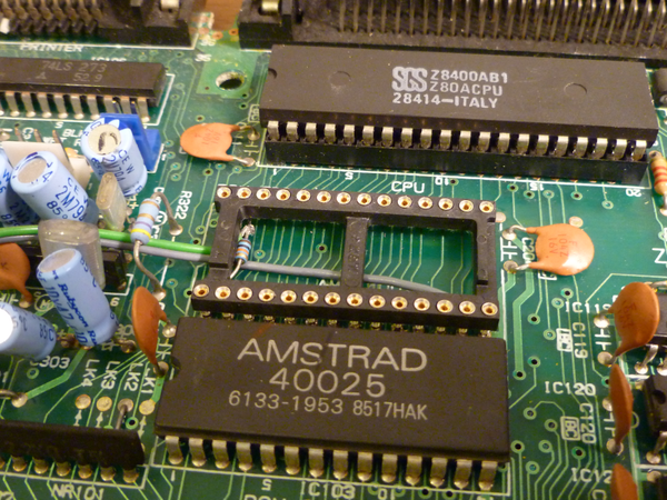
First you need to remove the 40015 IC from the mainboard. Tips on how to do this can be found here.
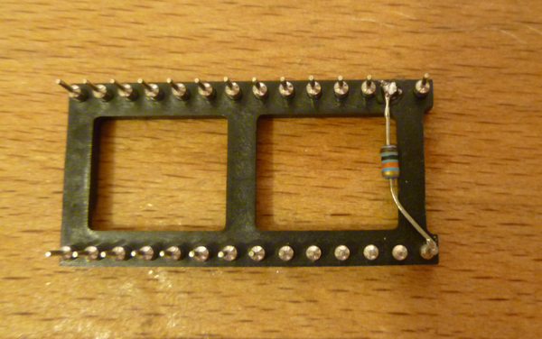
Next you will need to prepare a 28pin socket. To make the mod exactly like I have done, you should use a low-profile socket where the pins protrude below the sockets plastic.
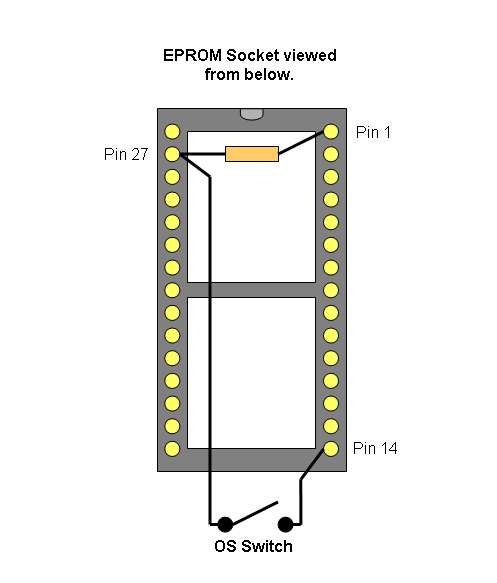
Pin 27 should be cut off completely below the plastic and a 10K resistor should be soldered between pin 27 and pin 1. This is a pull-up resistor to ensure that A14 of the EPROM is held at 5V when the OS switch is open.
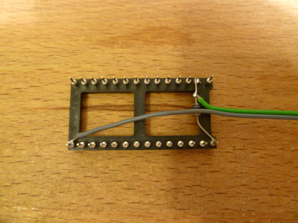
Next you need to solder a flylead to pin 14 and pin 27. These leads need to go to a standard normally open switch mounted on the CPCs casing.
Closing the switch will set A14 to zero and opening it sets A14 to one. This allows you to enable the upper or lower 16K of the EPROM and thus select which OS the CPC sees.
The following diagram gives a clearer picture of how the connections should be.
The socket now needs to be soldered onto the mainboard, but pin 27 should not make contact with the PCB track.
The EPROM should be burnt with whatever two OSs you wish to have, the first OS is saved from &0000 to &3FFF and the second OS should be located at &4000 to &7FFF.
The ROM image below is a single 32K file with AMSDOS and ParaDOS.
Bryce.
