Difference between revisions of "DDI Modification"
| (2 intermediate revisions by the same user not shown) | |||
| Line 1: | Line 1: | ||
== The Problem == | == The Problem == | ||
| − | The [[Amstrad_Disk_Drive|Amstrad DDI-1 Disc Interface]] was made to be used with Amstrad FD-1 Floppy Drives only. To deter users from using other drives Amstrad implemented two features to make standard PC drives incompatible: | + | The [[Amstrad_Disk_Drive|Amstrad DDI-1 Disc Interface]] was made to be used with [[Amstrad_Disk_Drive|Amstrad FD-1 Floppy Drives]] only. To deter users from using other drives Amstrad implemented two features to make standard PC drives incompatible: |
* The 34way cable to the floppy uses a non-standard pinout. | * The 34way cable to the floppy uses a non-standard pinout. | ||
| Line 23: | Line 23: | ||
The 3.5" Drive will still need to be connected with a standard 5V / 12V supply as usual and you will need to have modified it to send a ready signal. Additionally, PC drives are usually configured to be Drive B: (DS1), so the drive will also be seen as drive B: by the CPC. However, this can also usually be configured inside the floppy, so that the drive will function as drive A: on the CPC. | The 3.5" Drive will still need to be connected with a standard 5V / 12V supply as usual and you will need to have modified it to send a ready signal. Additionally, PC drives are usually configured to be Drive B: (DS1), so the drive will also be seen as drive B: by the CPC. However, this can also usually be configured inside the floppy, so that the drive will function as drive A: on the CPC. | ||
| + | |||
| + | == Links == | ||
| + | |||
| + | [http://www.pitsch.de/stuff/amiga/floppy.htm Enabling the Ready Signal] - German Site with instructions and photos of how to enable the ready signal for many common floppy drives. | ||
Latest revision as of 05:17, 21 April 2011
The Problem
The Amstrad DDI-1 Disc Interface was made to be used with Amstrad FD-1 Floppy Drives only. To deter users from using other drives Amstrad implemented two features to make standard PC drives incompatible:
- The 34way cable to the floppy uses a non-standard pinout.
- The DDI-1 gets its power from the FD-1, which a standard PC Drive can't do.
The Solution
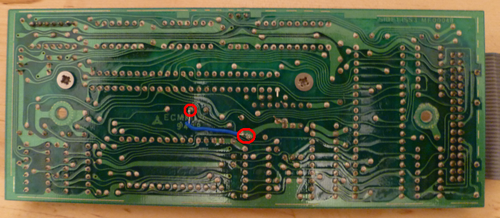
Getting power from the CPC instead of the FD-1 is a simple modification. A small bridge or wire needs to be added inside the DDI-1 so that the DDI-1 ICs are powered from the CPC. This connection can be seen in the picture below. The two points chosen are non-critical points ie: it's safe to solder here even if you're not a grandmaster of soldering. If you only ever intend using the DDI-1 with 3.5" drives, then a simple and permanent wire connection can be used. If you intend also using an FD-1 occasionally with the DDI-1, then you should use a switch or jumper here so that the connection can be disconnected.
Important: You cannot connect an FD-1 AND a 3.5" drive to the DDI-1 at the same time, even after these modifications have been made!
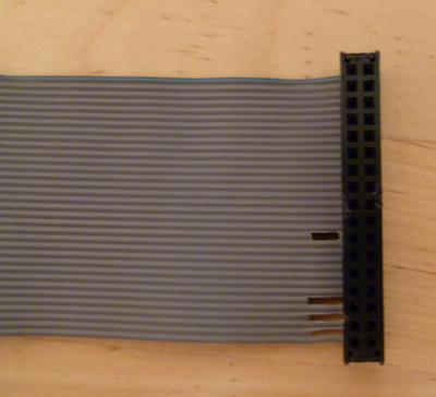
The second issue is the 34 way pinout. Firstly it's the wrong way around, but this can be easily solved by connecting it the wrong way to the Floppy Drive ie: Whereas normally Pin1 (usually marked as red or blue on the cable) is usually on the left when looking at the rear of the floppy drive, you should connect it with the blue wire on the right hand side. The next issue is the connector keyway. These are the small plastic tabs on the connector which ensure you connect the connector the right way around. These can either be removed from the original DDI-1 connector using a sharp knife, or as I chose, removing the original connector and replacing it with a standard floppy connector from an old PC flat cable. The last problem relates back to the fact that the DDI-1 gets its power from the FD-1. To achieve this, Amstrad uses four wires within the 34 way cable to supply the 5V. These particular wires would normally be connected to GND on a standard floppy, so leaving these connected would cause a short circuit and nothing would work. To get around this, I simply cut a piece out of each of these. The wires that need to be cut are: 21, 29, 31 and 33. I removed a section of each one just before the new connector, doing it this way means that the other connector on the cable is still connected as it was and can be used to connect an FD-1. This is what it then looks like:
The 3.5" Drive will still need to be connected with a standard 5V / 12V supply as usual and you will need to have modified it to send a ready signal. Additionally, PC drives are usually configured to be Drive B: (DS1), so the drive will also be seen as drive B: by the CPC. However, this can also usually be configured inside the floppy, so that the drive will function as drive A: on the CPC.
Links
Enabling the Ready Signal - German Site with instructions and photos of how to enable the ready signal for many common floppy drives.
Bryce.

