Difference between revisions of "LCD And Plasma TV Solution"
m |
|||
| Line 93: | Line 93: | ||
| − | [[File:MP2_PCB_Tracks.pdf]] - PCB Track Layout | + | [[File:MP2_PCB_Tracks.pdf]] - PCB Track Layout |
[[File:MP2_PCB_Layout.pdf]] - Component positions | [[File:MP2_PCB_Layout.pdf]] - Component positions | ||
Revision as of 17:23, 15 November 2009
Contents
Description
This project describes ways to get an improved quality picture from the Amstrad CPC (classic not plus) on a modern LCD or Plasma TV. After recently reading an article, that stated that the well-known CPC SCART cables don't work on Modern LCD / plasma TVs, I decided that I would investigate alternative options, because I was about to dump my last CRT for a plasma TV. I should mention at this stage, that the solution here, will not quite give you the same quality as a SCART cable on a CRT, but it is considerably better than the picture achieved by an MP1/2 setup and is very close to the SCART solution. With further improvements a SCART quality picture is possible using this method, but I will go into those details further down.
Warning / Disclaimer
This project involves opening and modifying a device which uses 240V AC. If you don't know what you're doing, then leave it to someone who does. Although the modifications do not involve the high-voltage areas of the circuit, extreme caution should be taken at all times and the unit should always be disconnected from the mains supply BEFORE the casing is opened and only re-connected after the case has been closed again.
Although I have taken the utmost care preparing this documentation, I do not guarantee that it is error free and I accept no responsibility for damage to anyone’s MP1/2, shiny new television, other personal equipment or injury inflicted on you or others.
The Theory
The Amstrad CPC produces an RGB signal with the signals Red, Green, Blue, Sync and Luminance. Using the SCART solution, all these signals are sent directly to a CRT TV to produce a rather crisp picture. Unfortunately this doesn't hold true for LCD and Plasma TVs. I haven't fully investigated why, but I would guess that it has something to do with the software implementation of how the TV converts analogue signals into picture data.
The old solution, using an MP1/2 gives a pretty low quality picture, which may have kept us happy back in the 80s, but it definitely won't do today. Luckily, there's something we can do about it, and if you happen to own an old MP1/2 still, then it won't even cost very much either. Below is a diagram of the modulation stages between a CPC and a TV using an MP1/2.
As you can see, the signal is being converted from RGB to Composite, then being modulated onto an RF signal (because that's all TVs understood back then) and then the TV just de-modulates the signal back to composite two metres further along the cable. By eliminating the two RF stages, which both have losses, noise and generally mess up the quality of the picture, we can get a much better picture from our trusty MP1/2. Luckily, modern TVs usually come with a composite input, which means we can easily bridge the two RF stages without making any changes to the TV. But don't worry if you don't own an MP1/2, further below is a circuit diagram of the RGB to composite modulator, which you can also build quite cheaply if you don't own an MP1/2.
After the conversion, the composite signal is tapped from the MP1/2 circuit and connected directly to the composite input of the TV, bridging the two RF stages.
Converting an MP1/2 to Composite
What you will need:
- A soldering iron and assorted electrical tools (cutters / screw-drivers / etc)
- A short length of coaxial cable or twisted wires
- A female cinch socket of your choice or male cinch connector
- A male-male composite connection cable
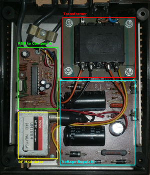
First we need to open the MP1/2, this is done by removing the four screws on the bottom of the unit in each corner. Do not remove the two large screws closer to the centre as these are there to support the transformer, which we don't need to disassemble. The picture below shows the innards of an MP1. In the top right corner you can see the transformer with the regulator circuit board below it. To the left is a small circuit board with the RGB to composite and RF conversion stages.
The top section of this board converts the RGB to composite and the small steel box houses the RF modulator. This is the circuit board we need to work on. By removing the three screws, we can carefully lift and turn the circuit board over (Remover the coax cable from the RF box to make things easier) and it should look something like this:
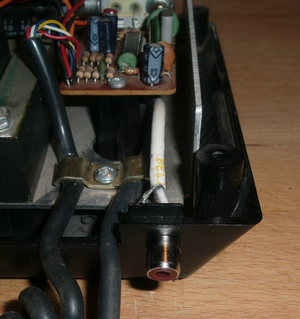
Using a short length of coaxial cable, we need to tap off the composite signal at the two points shown in the picture above. The outer shield of the coax cable should be twisted tightly and pre-tinned with solder beforehand, to ensure that no stray strands of the shield cause a short circuit. The shield is soldered to the earth track or the RF casing (Point A). The centre core of the coax is then soldered to the composite output of the circuit (Point B). Next we need to mount a female cinch socket. You can either use an inline connector which can be mounted on a fly-lead outside the casing or a surface mounted cinch socket which is mounted directly in the casing. I chose a surface mounted socket, because I find the solution neater, but you may prefer the fly-lead solution with female inline connector or an even longer fly-lead with a male cinch connector for direct connection to the TV. It's up to you. If you are using a surface mounted socket, it is also possible to use two normal wires to make the connection, but you should twist these around each other to avoid interference. When drilling holes in this type of plastic, a wood drill-bit should be used on a slow speed so that the plastic doesn't crack or melt in the process. Once you have made the connection to the connector / socket, carefully return the circuit board to its original position and replace the three mounting screws. Fortunately the circuit board is mounted at a slight angle, which means there's plenty of room for the additional connections. Make sure the new composite circuits are routed well away from the power circuitry and the transformer on the right, as a short circuit between these circuits would not only cost you your MP1/2 but most likely destroy your shiny new plasma TV along with it.
I also removed the old RF output cable completely, to neaten things up a little bit more and because I don’t intend using this output again.
Once you have mounted the connector / socket of your choice, it's just a matter of putting everything back together, connecting your CPC / MP1/2 setup to the composite input of your TV and enjoying the 42in / 50in / 'whatever your TV has' CPC display.
A note to beginners: The two points on the circuit board are not directly connected to the MC1377, so they are not considered to be critical points, so soldering a little bit too long shouldn’t destroy any components immediately.
Building Your Own RGB To Composite Converter
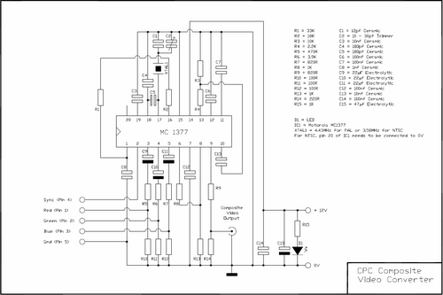
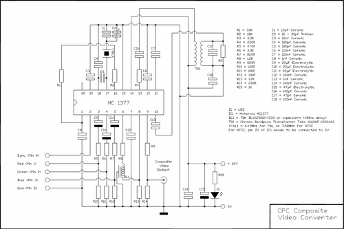
If you are not lucky enough to have an MP1/2 lying around at home, then you'll have to build your own. This circuit won't supply your CPC with the 5V or 12V it requires (A SCART cable doesn't either), it just converts the RGB to Composite. The circuit below is based on the Motorola MC1377 RGB to PAL/NTSC Encoder. It is almost identical to that found in an MP1/2 and is more or less the same as the application example found in the datasheet for the Motorola MC1377 with a few small changes made to reduce manufacturing costs. Almost everything that needs to be done is taken care of by the MC1377 with just a few external components to adjust the signal levels correctly and produce the frequency required, etc.
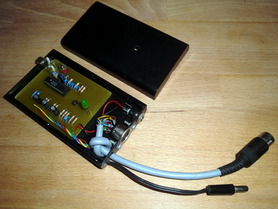
This circuit requires a 12V DC supply, which doesn't necessarily need to be regulated as the MC1377 has an integrated 8.2V regulator, but because the CPC has a 12V regulated supply, this is the easiest way to supply the circuit. I have included a male and female power connector in the design similar to those found on the CPC6128, so that the device can be placed in line with the 12V supply to the CPC. If you happen to own a CPC464 you will need an extra 12V supply for the converter. Below is a picture of the finished device.
Making It Cheaper
If you want to reduce the price even further, here are some things that you can consider:
- You will notice that I have added a thru-connector for the RGB signals also, this was to allow me to connect a CPC monitor to the computer at the same time, but is not necessary if you don't need this.
- The variable capacitor C2 is there to allow minor frequency adjustments (approx. +/- 1.0 kHz). Although this is technically required to fine tune the output frequency, most modern TVs are pretty much frequency insensitive, so to save money, this could be replaced with a fixed value capacitor of 10pf. But I have left it in, just in case some TVs still require adjustments to be made.
- The power on LED and associated resistor R15 are also a "nice to have" but are not required for the circuit to function correctly.
- If the circuit is built compact enough, it could be possible to integrate this circuit directly into the casing of a CPC6128/664 or CPC464 (with an additional 12V power input). This results in a very neat solution of a CPC with a direct composite output and also saves buying the casing, connectors and several other components, but be sure to mount the circuit securely, where it can't come in contact with the CPCs own circuit boards.
Resources
The following files are the PCB and component position layouts to construct the circuit above:
File:MP2 PCB Tracks.pdf - PCB Track Layout
File:MP2 PCB Layout.pdf - Component positions
The Result
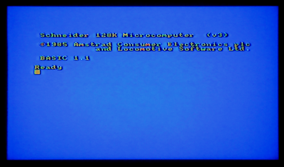
The screen below is on a 32in JVC LCD TV using the converted MP1 to produce the signal (Click picture for higher resolution)
Improving The Quality Further
The screen shot above, shows why I described it as "not quite" SCART quality. On close inspection you will notice that the edges of the text are still slightly jagged. This is more noticeable on LCD than on Plasma and can vary from TV to TV. The reason for this is that (most likely due to cost restrictions) Amstrad decided not to include a proper chroma coupling circuit. These extra components would better align the text edges. Unfortunately, these components are very difficult to find these days and because of this, I have also gone for the cheaper and easier solution instead. Should you be able to source these parts for a reasonable price, then you can make the following changes to the circuit, which will bring the image up to SCART quality. The additional components recommended by Motorola are:
- Colour Bandpass Transformer 166NNF-10264AG made by Toko
- Delay Line DL122301D-1533 made by TDK
If you find an alternative delay line (in an old TV perhaps), make sure that it is a high impedance part (1 - 1.5K) otherwise your circuit wont survive very long. You will also have to adjust the values of R8 and R13 to suit the impedance of the particular delay line you intend to use. I was unable to source either of these parts, so until I find another solution, I will have to live with jagged edges.
NTSC
If you live in a country which uses NTSC, you will have to make two slight adjustments to the circuits shown above. Firstly, XTAL1 needs to be a 3.58MHz crystal instead of the 4.43MHz shown above and you will also need to connect pin 20 of the MC1377 to ground. Other than that, the circuit should work exactly as with PAL, although I have not tested this, because I have no access to NTSC equipment.
Not Always The Solution
Having tested these two devices on several different TVs, I have discovered that some TVs are extremely sensitive about the accuracy of their composite signal and won’t produce a picture with this circuit. Particularly Panasonic Plasma TVs don’t seem to play along. If you do build either of these devices and are successful (or not), let me know which TV it worked on or not so that I can compile a compatibility list for others.
If you have any further questions regarding this project, please contact me through the Wiki Forum.
Bryce.


