Difference between revisions of "Schematics"
From CPCWiki - THE Amstrad CPC encyclopedia!
(Replacing Schematic for 464) |
|||
| (17 intermediate revisions by 5 users not shown) | |||
| Line 2: | Line 2: | ||
<gallery caption="System Schematics"> | <gallery caption="System Schematics"> | ||
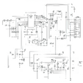
| − | File:Schaltplan_cpc_464.jpg|Amstrad CPC464 | + | File:464Schematic_new.png|Amstrad CPC464 (new) |
| − | File:CPC664_Schematic.png|Amstrad CPC664 | + | File:Schaltplan_cpc_464.jpg|Amstrad CPC464 (scan) |
| − | File:CPC6128_Schematic.png|Amstrad CPC6128 | + | File:CPC664_Schematic.png|Amstrad CPC664 (main) |
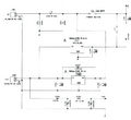
| + | File:CPC664 Disk Interface Schematic.png|Amstrad CPC664 (disc) | ||
| + | File:CPC6128_Schematic.png|Amstrad CPC6128 (main) | ||
| + | File:CPC6128 Disk Interface Schematic.png|Amstrad CPC6128 (disc) | ||
| + | File:CPC_Disc_Cassette_Schematic.gif|Disc And Cassette Schematics | ||
</gallery> | </gallery> | ||
| + | |||
| + | # HighRes scalable version of the CPC464 Schematics: [[Media:464SchematicRedraw_white.pdf|464SchematicRedraw_white.pdf]] | ||
| + | |||
| + | |||
| + | # A full KiCad 6 schematic and pcb layout for the MC0020x CPC6128 boards (featuring the "new" gate array and 24-pin data separator IC) is available at https://github.com/pelrun/cpc-schematics | ||
<gallery caption="Monitor Schematics"> | <gallery caption="Monitor Schematics"> | ||
File:GT64_Schematic.png|GT64 | File:GT64_Schematic.png|GT64 | ||
| + | File:GT65_Schematic.png|GT65 | ||
File:CTM640_Schematic.png|CTM640 | File:CTM640_Schematic.png|CTM640 | ||
| + | File:CTM644_Schematic.png|CTM644 | ||
</gallery> | </gallery> | ||
| Line 18: | Line 29: | ||
== CPC Plus Schematics == | == CPC Plus Schematics == | ||
| − | <gallery caption="Original Scans (high-resolution, with lots of blank space"> | + | <gallery caption="Original Scans (high-resolution, with lots of blank space)"> |
File:CPC_Plus_CPU_Schematic.jpg|CPU Schematic | File:CPC_Plus_CPU_Schematic.jpg|CPU Schematic | ||
File:CPC_Plus_Asic_Schematic.GIF|Asic Schematic | File:CPC_Plus_Asic_Schematic.GIF|Asic Schematic | ||
| Line 30: | Line 41: | ||
File:Edited CPC_Plus_Vid_Mem_Schematic.gif|Video and Memory Schematic | File:Edited CPC_Plus_Vid_Mem_Schematic.gif|Video and Memory Schematic | ||
File:Edited CPC_Plus_Cassette_Schematic.gif|Cassette Schematic | File:Edited CPC_Plus_Cassette_Schematic.gif|Cassette Schematic | ||
| + | </gallery> | ||
| + | |||
| + | <gallery caption="Monitor Schematics"> | ||
| + | File:MM12_Schematic.gif|MM12 Schematic | ||
| + | File:CM14_Power_Sound_Schematic.gif|CM14 Power And Sound Schematic | ||
| + | File:CM14_Video_Schematic.gif|CM14 Video Schematic | ||
| + | </gallery> | ||
| + | |||
| + | == GX4000 Schematics == | ||
| + | |||
| + | <gallery caption="System Schematics"> | ||
| + | File:GX4000_CPU_Schematic.png|CPU Schematic | ||
| + | File:GX4000_ASIC_Schematic.png|Asic Schematic | ||
| + | File:GX4000_Memory_Video_Schematic.png|Video and Memory Schematic | ||
| + | File:GX4000_RGB_Schematic.png|RGB Conversion Schematic | ||
| + | File:GX4000_Power_Schematic.png|Power Supply Schematic | ||
| + | </gallery> | ||
| + | |||
| + | <gallery caption="GX4000 - Edited version (lower resolution, less white space)"> | ||
| + | File:Edited GX4000 ASIC Schematic.gif|ASIC Schematic | ||
| + | File:Edited GX4000 Vid Mem Cpu Schematic.gif|CPU Video Memory | ||
| + | File:Edited GX4000 RGB Power Schematic.gif|RGB and Power (PAL) | ||
| + | File:Edited GX4000 French Schematic.gif|RGB and Power (French) | ||
| + | |||
</gallery> | </gallery> | ||
| Line 43: | Line 78: | ||
File:Kcc component map modulator.gif|Component Map (Modulator) | File:Kcc component map modulator.gif|Component Map (Modulator) | ||
</gallery> | </gallery> | ||
| + | |||
| + | == Aleste 520EX Schematics (Russian CPC clone) == | ||
| + | |||
| + | <gallery> | ||
| + | File:Aleste-Schematic1.gif|Schematic 1/4 | ||
| + | File:Aleste-Schematic2.gif|Schematic 2/4 | ||
| + | File:Aleste-Schematic3.gif|Schematic 3/4 | ||
| + | File:Aleste-Schematic4.gif|Schematic 4/4 | ||
| + | File:Aleste-Component-Map.gif|Component Map | ||
| + | </gallery> | ||
| + | |||
| + | For reference, the original '''unedited''' schematics are here: | ||
| + | [[Media:Black-Aleste-Schematic1.gif|Sheet 1]], | ||
| + | [[Media:Black-Aleste-Schematic2.gif|Sheet 2]], | ||
| + | [[Media:Black-Aleste-Schematic3.gif|Sheet 3]], | ||
| + | [[Media:Black-Aleste-Schematic4.gif|Sheet 4]], and | ||
| + | [[Media:Black-Aleste-Component-Map.gif|Component Map]] | ||
== Additional Hardware == | == Additional Hardware == | ||
| Line 52: | Line 104: | ||
* '''Note''' - Further schematics are found in the [[Service Manuals]]. | * '''Note''' - Further schematics are found in the [[Service Manuals]]. | ||
| − | [[Category:Hardware]][[Category:CPC Internal Components]] | + | [[Category:Hardware| ]][[Category:CPC Internal Components| ]][[Category:Amstrad CPC media]][[Category:Picture Gallery]][[Category:Electronic Component| ]][[Category:Clones|*]][[Category:CPC Plus|*]] |
Latest revision as of 05:35, 12 April 2024
Contents
CPC Classic Schematics
- System Schematics
- HighRes scalable version of the CPC464 Schematics: 464SchematicRedraw_white.pdf
- A full KiCad 6 schematic and pcb layout for the MC0020x CPC6128 boards (featuring the "new" gate array and 24-pin data separator IC) is available at https://github.com/pelrun/cpc-schematics
- Monitor Schematics
- Disk Drive Interface Schematics
CPC Plus Schematics
- Original Scans (high-resolution, with lots of blank space)
- Edited (lower resolution, less blank space, more concentrated info)
- Monitor Schematics
GX4000 Schematics
- System Schematics
- GX4000 - Edited version (lower resolution, less white space)
KC Compact Schematics (East German CPC clone)
Aleste 520EX Schematics (Russian CPC clone)
For reference, the original unedited schematics are here: Sheet 1, Sheet 2, Sheet 3, Sheet 4, and Component Map
Additional Hardware
- 3 1/2" & 5 1/4" Disk Drives (errr. no schematics here, no pinouts, nothing?)
- Peripherals (contains schematics - as far as any do exist)
- Joystick Y-cables (with schematics)
- TV Scart cable (with schematics)
- Note - Further schematics are found in the Service Manuals.


