Difference between revisions of "765 FDC"
(→FDC Command Table (15 commands)) |
|||
| (15 intermediate revisions by the same user not shown) | |||
| Line 3: | Line 3: | ||
The ports used by Amstrad and compatible interfaces use: | The ports used by Amstrad and compatible interfaces use: | ||
| − | * Port | + | * Port &FA7E - Floppy Motor On/Off Flipflop |
| − | * Port | + | * Port &FB7E - FDC 765 Main Status Register (read only) |
| − | * Port | + | * Port &FB7F - FDC 765 Data Register (read/write) |
The [[Vortex Disc Drives|Vortex disc interface]] uses other ports. See its dedicated wiki page. | The [[Vortex Disc Drives|Vortex disc interface]] uses other ports. See its dedicated wiki page. | ||
| Line 33: | Line 33: | ||
== Accessing the FDC 765 == | == Accessing the FDC 765 == | ||
| − | The | + | The Main Status Register (Port &FB7E) signalizes when the FDC is ready to send/receive the next byte through the Data Register. |
| − | + | ||
| − | + | The Data Register (Port &FB7F) is used to write Commands and Parameters, to read/write data bytes, and to receive result bytes. These three operations are called Command-, Execution-, and Result-Phase. | |
| − | + | <br> | |
| + | |||
| + | === Command Phase === | ||
| + | |||
| + | A command consists of a command byte (eventually including the MT, MF, SK bits), and up to 8 parameter bytes. | ||
| + | |||
| + | <br> | ||
| + | |||
| + | === Execution Phase === | ||
| + | |||
| + | During this phase, the actual data is transferred (if any). Usually that are the data bytes for the read/written sector(s), except for the Format Track Command, in that case 4 bytes for each sector are transferred. | ||
| + | |||
| + | During data transfers between the FDC and the processor, the FDC must me serviced every 26us (for MFM mode with CPC timings) or the FDC terminates the FDC command. | ||
| + | |||
| + | <br> | ||
| + | |||
| + | === Result Phase === | ||
| + | |||
| + | Returns up to 7 result bytes (depending on the command) that are containing status information. The Recalibrate and Seek Track commands do not return result bytes directly, instead the program must wait until the Main Status Register signalizes that the command has been completed, and then it must (!) send a Sense Interrupt State command to 'terminate' the Seek/Recalibrate command. | ||
| − | + | During the result phase, all the result bytes must be read. The FDC will not accept a new command until all the result bytes are read. | |
<br> | <br> | ||
| Line 445: | Line 462: | ||
| command byte 0 || colspan="3" style="text-align: center;" | x || 0 || 1 || 1 || 1 || 1 | | command byte 0 || colspan="3" style="text-align: center;" | x || 0 || 1 || 1 || 1 || 1 | ||
|- | |- | ||
| − | | command byte 1 || colspan="5" style="text-align: center;" | x || HD || colspan="2" style="text-align: center;" | US | + | | command byte 1 || colspan="5" style="text-align: center;" | x || HD|| colspan="2" style="text-align: center;" | US |
|- | |- | ||
| command byte 2 || colspan="8" | NCN: new cylinder number | | command byte 2 || colspan="8" | NCN: new cylinder number | ||
| Line 513: | Line 530: | ||
Notes: | Notes: | ||
* Format Track: The processor must supply C, H, R, N to the FDC for each sector during execution phase | * Format Track: The processor must supply C, H, R, N to the FDC for each sector during execution phase | ||
| − | * Recalibrate: Walks up to 77 tracks, 80tr-drives may need second | + | * Recalibrate: Walks up to 77 tracks, 80tr-drives may need a second recalibrate if failed |
| − | * Seek / Recalibrate: All read/write commands will be disabled until | + | * Seek / Recalibrate: All read/write commands will be disabled until successful sense interrupt |
* Specify: All timings will be doubled on CPC because the FDC runs at 4MHz instead of 8MHz for the datasheet | * Specify: All timings will be doubled on CPC because the FDC runs at 4MHz instead of 8MHz for the datasheet | ||
| Line 521: | Line 538: | ||
== FDC Status Registers == | == FDC Status Registers == | ||
| − | The Main Status register can be always read through Port FB7E. The other four Status Registers cannot be read directly, instead they are returned through the data register as result bytes in response to specific commands. | + | The Main Status register can be always read through Port &FB7E. The other four Status Registers cannot be read directly, instead they are returned through the data register as result bytes in response to specific commands. |
| − | Main Status Register (Port FB7E) | + | Main Status Register (Port &FB7E): |
b0..3 DB FDD0..3 Busy (seek/recalib active, until succesful sense intstat) | b0..3 DB FDD0..3 Busy (seek/recalib active, until succesful sense intstat) | ||
| Line 531: | Line 548: | ||
b7 RQM Request For Master (1=ready for next byte) (see b6 for direction) | b7 RQM Request For Master (1=ready for next byte) (see b6 for direction) | ||
| − | Status Register 0 | + | Status Register 0: |
b0,1 US Unit Select (driveno during interrupt) | b0,1 US Unit Select (driveno during interrupt) | ||
| Line 541: | Line 558: | ||
or senseint with no int occured, 3=aborted:disc removed etc.) | or senseint with no int occured, 3=aborted:disc removed etc.) | ||
| − | Status Register 1 | + | Status Register 1: |
b0 MA Missing Address Mark (Sector_ID or DAM not found) | b0 MA Missing Address Mark (Sector_ID or DAM not found) | ||
| Line 551: | Line 568: | ||
b7 EN End of Track (set past most read/write commands) (see IC) | b7 EN End of Track (set past most read/write commands) (see IC) | ||
| − | Status Register 2 | + | Status Register 2: |
b0 MD Missing Address Mark in Data Field (DAM not found) | b0 MD Missing Address Mark in Data Field (DAM not found) | ||
| Line 562: | Line 579: | ||
b7 0 Not Used | b7 0 Not Used | ||
| − | Status Register 3 | + | Status Register 3: |
b0,1 US Unit Select (pin 28,29 of FDC) | b0,1 US Unit Select (pin 28,29 of FDC) | ||
| Line 571: | Line 588: | ||
b6 WP Write Protected (write protected) | b6 WP Write Protected (write protected) | ||
b7 FT Fault (if supported: 1=Drive failure) | b7 FT Fault (if supported: 1=Drive failure) | ||
| + | |||
| + | <br> | ||
| + | |||
| + | == C, H, R, N values at result phase == | ||
| + | |||
| + | If the processor terminates a read (or write) operation in the FDC, then the ID information in the Result phase is dependent upon the state of the MT bit and EOT byte: | ||
| + | |||
| + | {| class="wikitable" | ||
| + | |- | ||
| + | ! rowspan="2" | MT !! rowspan="2" | HD !! rowspan="2" | Final Sector Transferred to Processor !! colspan="4" style="text-align: center;" | ID Information at Result Phase | ||
| + | |- | ||
| + | ! C !! H !! R !! N | ||
| + | |- | ||
| + | | 0 || 0 || style="text-align: center;" | Less than EOT || - || - || R + 1 || - | ||
| + | |- | ||
| + | | 0 || 0 || style="text-align: center;" | Equal to EOT || C + 1 || - || 0 || - | ||
| + | |- | ||
| + | | 0 || 1 || style="text-align: center;" | Less than EOT || - || - || R + 1 || - | ||
| + | |- | ||
| + | | 0 || 1 || style="text-align: center;" | Equal to EOT || C + 1 || - || 0 || - | ||
| + | |- | ||
| + | | 1 || 0 || style="text-align: center;" | Less than EOT || - || - || R + 1 || - | ||
| + | |- | ||
| + | | 1 || 0 || style="text-align: center;" | Equal to EOT || - || LSB || 0 || - | ||
| + | |- | ||
| + | | 1 || 1 || style="text-align: center;" | Less than EOT || - || - || R + 1 || - | ||
| + | |- | ||
| + | | 1 || 1 || style="text-align: center;" | Equal to EOT || C + 1 || LSB || 0 || - | ||
| + | |} | ||
| + | |||
| + | * An empty cell means it is the same value as the one at the beginning of command execution | ||
| + | * LSB (Least Significant Bit): The least significant bit of H is complemented | ||
<br> | <br> | ||
== Motor On/Off Flipflop == | == Motor On/Off Flipflop == | ||
| − | Writing 00h to Port | + | Writing 00h to Port &FA7E turns all disk drive motors off, writing 01h turns all motors on. It is not possible to turn on/off the motor of a specific drive separately. |
An exception are the Vortex F1-S, F1-D, M1-S and M1-D drives. (How are they different?) | An exception are the Vortex F1-S, F1-D, M1-S and M1-D drives. (How are they different?) | ||
| Line 671: | Line 720: | ||
*[http://quasar.cpcscene.net/doku.php?id=assem:fdc Quasar FDC documentation (in french)] | *[http://quasar.cpcscene.net/doku.php?id=assem:fdc Quasar FDC documentation (in french)] | ||
*[https://64nops.wordpress.com/2021/07/04/a-la-decouverte-du-fdc/ FDC blog articles (in french)] | *[https://64nops.wordpress.com/2021/07/04/a-la-decouverte-du-fdc/ FDC blog articles (in french)] | ||
| − | *[https://info-coach.fr/atari/hardware/FD-Hard.php Atari ST Floppy | + | *[https://info-coach.fr/atari/hardware/FD-Hard.php Atari ST Floppy Drive hardware analysis] |
[[Category:CPC Internal Components]][[Category:Programming]][[Category:DATA Storage]][[Category:Electronic Component]] | [[Category:CPC Internal Components]][[Category:Programming]][[Category:DATA Storage]][[Category:Electronic Component]] | ||
Latest revision as of 23:19, 4 July 2024
µPD765 - Floppy Disc Controller (used in DDI-1 and CPC 664/6128).
The ports used by Amstrad and compatible interfaces use:
- Port &FA7E - Floppy Motor On/Off Flipflop
- Port &FB7E - FDC 765 Main Status Register (read only)
- Port &FB7F - FDC 765 Data Register (read/write)
The Vortex disc interface uses other ports. See its dedicated wiki page.
Contents
- 1 IC Models used in CPC
- 2 Accessing the FDC 765
- 3 FDC Command Table (15 commands)
- 4 FDC Status Registers
- 5 C, H, R, N values at result phase
- 6 Motor On/Off Flipflop
- 7 Unconnected Pins
- 8 Ready / Disk Changed signal
- 9 Notes
- 10 FDC Track Format
- 11 Internal details of the chip
- 12 FDC Block Diagram
- 13 Generic System Diagram
- 14 PC to CPC floppy connector
- 15 FDD Block Diagram
- 16 Datasheets
- 17 External links
IC Models used in CPC
More than one manufacturer made 765 compatible ICs. These are the ones known to be used in the CPC by looking at pictures of CPC mainboards.
All should operate almost identically.
- Zilog Z0765A08PSC
- NEC D765AC-2
- NEC D765AC
- UMC UM8272A
The following data seperators are used:
- FDC9216
- SED9420C
The CPC464, CPC472, 464 Plus and GX4000 are not equipped with a FDC chip.
Accessing the FDC 765
The Main Status Register (Port &FB7E) signalizes when the FDC is ready to send/receive the next byte through the Data Register.
The Data Register (Port &FB7F) is used to write Commands and Parameters, to read/write data bytes, and to receive result bytes. These three operations are called Command-, Execution-, and Result-Phase.
Command Phase
A command consists of a command byte (eventually including the MT, MF, SK bits), and up to 8 parameter bytes.
Execution Phase
During this phase, the actual data is transferred (if any). Usually that are the data bytes for the read/written sector(s), except for the Format Track Command, in that case 4 bytes for each sector are transferred.
During data transfers between the FDC and the processor, the FDC must me serviced every 26us (for MFM mode with CPC timings) or the FDC terminates the FDC command.
Result Phase
Returns up to 7 result bytes (depending on the command) that are containing status information. The Recalibrate and Seek Track commands do not return result bytes directly, instead the program must wait until the Main Status Register signalizes that the command has been completed, and then it must (!) send a Sense Interrupt State command to 'terminate' the Seek/Recalibrate command.
During the result phase, all the result bytes must be read. The FDC will not accept a new command until all the result bytes are read.
FDC Command Table (15 commands)
| D7 | D6 | D5 | D4 | D3 | D2 | D1 | D0 | |
|---|---|---|---|---|---|---|---|---|
| command byte 0 | MT | MF | SK | 0 | 0 | 1 | 1 | 0 |
| command byte 1 | x | HD | US | |||||
| command byte 2 | C: cylinder number | |||||||
| command byte 3 | H: head number | |||||||
| command byte 4 | R: sector number | |||||||
| command byte 5 | N: bytes per sector | |||||||
| command byte 6 | EOT: end of track (ie. last sector in track) | |||||||
| command byte 7 | GPL: gap 3 length | |||||||
| command byte 8 | DTL: data length (if command byte 5==0) | |||||||
| Execution | Data-transfer from the FDD | |||||||
| result byte 0 | ST0: status register 0 | |||||||
| result byte 1 | ST1: status register 1 | |||||||
| result byte 2 | ST2: status register 2 | |||||||
| result byte 3 | C: cylinder number | |||||||
| result byte 4 | H: head number | |||||||
| result byte 5 | R: sector number | |||||||
| result byte 6 | N: bytes per sector | |||||||
| D7 | D6 | D5 | D4 | D3 | D2 | D1 | D0 | |
|---|---|---|---|---|---|---|---|---|
| command byte 0 | MT | MF | SK | 0 | 1 | 1 | 0 | 0 |
| command byte 1 | x | HD | US | |||||
| command byte 2 | C: cylinder number | |||||||
| command byte 3 | H: head number | |||||||
| command byte 4 | R: sector number | |||||||
| command byte 5 | N: bytes per sector | |||||||
| command byte 6 | EOT: end of track (ie. last sector in track) | |||||||
| command byte 7 | GPL: gap 3 length | |||||||
| command byte 8 | DTL: data length (if command byte 5==0) | |||||||
| Execution | Data-transfer from the FDD | |||||||
| result byte 0 | ST0: status register 0 | |||||||
| result byte 1 | ST1: status register 1 | |||||||
| result byte 2 | ST2: status register 2 | |||||||
| result byte 3 | C: cylinder number | |||||||
| result byte 4 | H: head number | |||||||
| result byte 5 | R: sector number | |||||||
| result byte 6 | N: bytes per sector | |||||||
| D7 | D6 | D5 | D4 | D3 | D2 | D1 | D0 | |
|---|---|---|---|---|---|---|---|---|
| command byte 0 | MT | MF | x | 0 | 0 | 1 | 0 | 1 |
| command byte 1 | x | HD | US | |||||
| command byte 2 | C: cylinder number | |||||||
| command byte 3 | H: head number | |||||||
| command byte 4 | R: sector number | |||||||
| command byte 5 | N: bytes per sector | |||||||
| command byte 6 | EOT: end of track (ie. last sector in track) | |||||||
| command byte 7 | GPL: gap 3 length | |||||||
| command byte 8 | DTL: data length (if command byte 5==0) | |||||||
| Execution | Data-transfer to the FDD | |||||||
| result byte 0 | ST0: status register 0 | |||||||
| result byte 1 | ST1: status register 1 | |||||||
| result byte 2 | ST2: status register 2 | |||||||
| result byte 3 | C: cylinder number | |||||||
| result byte 4 | H: head number | |||||||
| result byte 5 | R: sector number | |||||||
| result byte 6 | N: bytes per sector | |||||||
| D7 | D6 | D5 | D4 | D3 | D2 | D1 | D0 | |
|---|---|---|---|---|---|---|---|---|
| command byte 0 | MT | MF | x | 0 | 1 | 0 | 0 | 1 |
| command byte 1 | x | HD | US | |||||
| command byte 2 | C: cylinder number | |||||||
| command byte 3 | H: head number | |||||||
| command byte 4 | R: sector number | |||||||
| command byte 5 | N: bytes per sector | |||||||
| command byte 6 | EOT: end of track (ie. last sector in track) | |||||||
| command byte 7 | GPL: gap 3 length | |||||||
| command byte 8 | DTL: data length (if command byte 5==0) | |||||||
| Execution | Data-transfer to the FDD | |||||||
| result byte 0 | ST0: status register 0 | |||||||
| result byte 1 | ST1: status register 1 | |||||||
| result byte 2 | ST2: status register 2 | |||||||
| result byte 3 | C: cylinder number | |||||||
| result byte 4 | H: head number | |||||||
| result byte 5 | R: sector number | |||||||
| result byte 6 | N: bytes per sector | |||||||
| D7 | D6 | D5 | D4 | D3 | D2 | D1 | D0 | |
|---|---|---|---|---|---|---|---|---|
| command byte 0 | x | MF | SK | 0 | 0 | 0 | 1 | 0 |
| command byte 1 | x | HD | US | |||||
| command byte 2 | C: cylinder number | |||||||
| command byte 3 | H: head number | |||||||
| command byte 4 | R: sector number | |||||||
| command byte 5 | N: bytes per sector | |||||||
| command byte 6 | EOT: end of track (ie. last sector in track) | |||||||
| command byte 7 | GPL: gap 3 length | |||||||
| command byte 8 | DTL: data length (if command byte 5==0) | |||||||
| Execution | FDC reads all data fields from index hole to EOT | |||||||
| result byte 0 | ST0: status register 0 | |||||||
| result byte 1 | ST1: status register 1 | |||||||
| result byte 2 | ST2: status register 2 | |||||||
| result byte 3 | C: cylinder number | |||||||
| result byte 4 | H: head number | |||||||
| result byte 5 | R: sector number | |||||||
| result byte 6 | N: bytes per sector | |||||||
| D7 | D6 | D5 | D4 | D3 | D2 | D1 | D0 | |
|---|---|---|---|---|---|---|---|---|
| command byte 0 | x | MF | x | 0 | 1 | 0 | 1 | 0 |
| command byte 1 | x | HD | US | |||||
| Execution | The first correct ID information on the cylinder is stored in data register | |||||||
| result byte 0 | ST0: status register 0 | |||||||
| result byte 1 | ST1: status register 1 | |||||||
| result byte 2 | ST2: status register 2 | |||||||
| result byte 3 | C: cylinder number | |||||||
| result byte 4 | H: head number | |||||||
| result byte 5 | R: sector number | |||||||
| result byte 6 | N: bytes per sector | |||||||
| D7 | D6 | D5 | D4 | D3 | D2 | D1 | D0 | |
|---|---|---|---|---|---|---|---|---|
| command byte 0 | x | MF | x | 0 | 1 | 1 | 0 | 1 |
| command byte 1 | x | HD | US | |||||
| command byte 2 | N: bytes per sector | |||||||
| command byte 3 | SC: sectors per track | |||||||
| command byte 4 | GPL: gap 3 length | |||||||
| command byte 5 | D: filler pattern to write in each byte | |||||||
| Execution | FDC formats an entire track | |||||||
| result byte 0 | ST0: status register 0 | |||||||
| result byte 1 | ST1: status register 1 | |||||||
| result byte 2 | ST2: status register 2 | |||||||
| result byte 3 | C: cylinder number | |||||||
| result byte 4 | H: head number | |||||||
| result byte 5 | R: sector number | |||||||
| result byte 6 | N: bytes per sector | |||||||
| D7 | D6 | D5 | D4 | D3 | D2 | D1 | D0 | |
|---|---|---|---|---|---|---|---|---|
| command byte 0 | MT | MF | SK | 1 | 0 | 0 | 0 | 1 |
| command byte 1 | x | HD | US | |||||
| command byte 2 | C: cylinder number | |||||||
| command byte 3 | H: head number | |||||||
| command byte 4 | R: sector number | |||||||
| command byte 5 | N: bytes per sector | |||||||
| command byte 6 | EOT: end of track (ie. last sector in track) | |||||||
| command byte 7 | GPL: gap 3 length | |||||||
| command byte 8 | STP: scan test (1=scan contiguous, 2=scan alternate) | |||||||
| Execution | Data compared between the FDD and main-system | |||||||
| result byte 0 | ST0: status register 0 | |||||||
| result byte 1 | ST1: status register 1 | |||||||
| result byte 2 | ST2: status register 2 | |||||||
| result byte 3 | C: cylinder number | |||||||
| result byte 4 | H: head number | |||||||
| result byte 5 | R: sector number | |||||||
| result byte 6 | N: bytes per sector | |||||||
| D7 | D6 | D5 | D4 | D3 | D2 | D1 | D0 | |
|---|---|---|---|---|---|---|---|---|
| command byte 0 | MT | MF | SK | 1 | 1 | 0 | 0 | 1 |
| command byte 1 | x | HD | US | |||||
| command byte 2 | C: cylinder number | |||||||
| command byte 3 | H: head number | |||||||
| command byte 4 | R: sector number | |||||||
| command byte 5 | N: bytes per sector | |||||||
| command byte 6 | EOT: end of track (ie. last sector in track) | |||||||
| command byte 7 | GPL: gap 3 length | |||||||
| command byte 8 | STP: scan test (1=scan contiguous, 2=scan alternate) | |||||||
| Execution | Data compared between the FDD and main-system | |||||||
| result byte 0 | ST0: status register 0 | |||||||
| result byte 1 | ST1: status register 1 | |||||||
| result byte 2 | ST2: status register 2 | |||||||
| result byte 3 | C: cylinder number | |||||||
| result byte 4 | H: head number | |||||||
| result byte 5 | R: sector number | |||||||
| result byte 6 | N: bytes per sector | |||||||
| D7 | D6 | D5 | D4 | D3 | D2 | D1 | D0 | |
|---|---|---|---|---|---|---|---|---|
| command byte 0 | MT | MF | SK | 1 | 1 | 1 | 0 | 1 |
| command byte 1 | x | HD | US | |||||
| command byte 2 | C: cylinder number | |||||||
| command byte 3 | H: head number | |||||||
| command byte 4 | R: sector number | |||||||
| command byte 5 | N: bytes per sector | |||||||
| command byte 6 | EOT: end of track (ie. last sector in track) | |||||||
| command byte 7 | GPL: gap 3 length | |||||||
| command byte 8 | STP: scan test (1=scan contiguous, 2=scan alternate) | |||||||
| Execution | Data compared between the FDD and main-system | |||||||
| result byte 0 | ST0: status register 0 | |||||||
| result byte 1 | ST1: status register 1 | |||||||
| result byte 2 | ST2: status register 2 | |||||||
| result byte 3 | C: cylinder number | |||||||
| result byte 4 | H: head number | |||||||
| result byte 5 | R: sector number | |||||||
| result byte 6 | N: bytes per sector | |||||||
| D7 | D6 | D5 | D4 | D3 | D2 | D1 | D0 | |
|---|---|---|---|---|---|---|---|---|
| command byte 0 | x | 0 | 0 | 1 | 1 | 1 | ||
| command byte 1 | x | US | ||||||
| Execution | Head retracted to track 0 | |||||||
| D7 | D6 | D5 | D4 | D3 | D2 | D1 | D0 | |
|---|---|---|---|---|---|---|---|---|
| command byte 0 | x | 0 | 1 | 1 | 1 | 1 | ||
| command byte 1 | x | HD | US | |||||
| command byte 2 | NCN: new cylinder number | |||||||
| Execution | Head is positioned over proper cylinder | |||||||
| D7 | D6 | D5 | D4 | D3 | D2 | D1 | D0 | |
|---|---|---|---|---|---|---|---|---|
| command byte 0 | x | 0 | 1 | 0 | 0 | 0 | ||
| result byte 0 | ST0: status register 0 | |||||||
| result byte 1 | PCN: present cylinder number | |||||||
| D7 | D6 | D5 | D4 | D3 | D2 | D1 | D0 | |
|---|---|---|---|---|---|---|---|---|
| command byte 0 | x | 0 | 0 | 1 | 0 | 0 | ||
| command byte 1 | x | HD | US | |||||
| result byte 0 | ST3: status register 3 | |||||||
| D7 | D6 | D5 | D4 | D3 | D2 | D1 | D0 | |
|---|---|---|---|---|---|---|---|---|
| command byte 0 | x | 0 | 0 | 0 | 1 | 1 | ||
| command byte 1 | SRT | HUT | ||||||
| command byte 2 | HLT | ND | ||||||
| D7 | D6 | D5 | D4 | D3 | D2 | D1 | D0 | |
|---|---|---|---|---|---|---|---|---|
| command byte 0 | x | Invalid Codes | ||||||
| result byte 0 | ST0: status register 0 | |||||||
Abbreviations used:
- MT = Multi-track (continue multi-sector function on other head)
- MF = MFM mode (1 = Double Density)
- SK = Skip deleted-data address mark (set if sectors with deleted DAM shall be skipped)
- HD = Head number select
- US = Unit select (drive select)
- HLT = Head Load Time: 2 to 254ms in 2ms increments
- HUT = Head Unload Time: 16 to 240ms in 16ms increments
- SRT = Step Rate Time: 1 to 16ms in 1ms increments (F = 1ms, E = 2ms, etc.)
- ND = Non-DMA mode
Notes:
- Format Track: The processor must supply C, H, R, N to the FDC for each sector during execution phase
- Recalibrate: Walks up to 77 tracks, 80tr-drives may need a second recalibrate if failed
- Seek / Recalibrate: All read/write commands will be disabled until successful sense interrupt
- Specify: All timings will be doubled on CPC because the FDC runs at 4MHz instead of 8MHz for the datasheet
FDC Status Registers
The Main Status register can be always read through Port &FB7E. The other four Status Registers cannot be read directly, instead they are returned through the data register as result bytes in response to specific commands.
Main Status Register (Port &FB7E):
 b0..3  DB   FDD0..3 Busy (seek/recalib active, until succesful sense intstat)
 b4     CB   FDC Busy (still in command-, execution- or result-phase)
 b5     EXM  Execution Mode (still in execution-phase, non_DMA_only)
 b6     DIO  Data Input/Output (0=CPU->FDC, 1=FDC->CPU) (see b7)
 b7     RQM  Request For Master (1=ready for next byte) (see b6 for direction)
Status Register 0:
 b0,1   US   Unit Select (driveno during interrupt)
 b2     HD   Head Address (head during interrupt)
 b3     NR   Not Ready (drive not ready or non-existing 2nd head selected)
 b4     EC   Equipment Check (drive failure or recalibrate failed (retry))
 b5     SE   Seek End (Set if seek-command completed)
 b6,7   IC   Interrupt Code (0=OK, 1=aborted:readfail/OK if EN, 2=unknown cmd
             or senseint with no int occured, 3=aborted:disc removed etc.)
Status Register 1:
 b0     MA   Missing Address Mark (Sector_ID or DAM not found)
 b1     NW   Not Writeable (tried to write/format disc with wprot_tab=on)
 b2     ND   No Data (Sector_ID not found, CRC fail in ID_field)
 b3,6   0    Not used
 b4     OR   Over Run (CPU too slow in execution-phase (ca. 26us/Byte))
 b5     DE   Data Error (CRC-fail in ID- or Data-Field)
 b7     EN   End of Track (set past most read/write commands) (see IC)
Status Register 2:
 b0     MD   Missing Address Mark in Data Field (DAM not found)
 b1     BC   Bad Cylinder (read/programmed track-ID different and read-ID = FF)
 b2     SN   Scan Not Satisfied (no fitting sector found)
 b3     SH   Scan Equal Hit (equal)
 b4     WC   Wrong Cylinder (read/programmed track-ID different) (see b1)
 b5     DD   Data Error in Data Field (CRC-fail in data-field)
 b6     CM   Control Mark (read/scan command found sector with deleted DAM)
 b7     0    Not Used
Status Register 3:
 b0,1   US   Unit Select (pin 28,29 of FDC)
 b2     HD   Head Address (pin 27 of FDC)
 b3     TS   Two Side (0=yes, 1=no (!))
 b4     T0   Track 0 (on track 0 we are)
 b5     RY   Ready (drive ready signal)
 b6     WP   Write Protected (write protected)
 b7     FT   Fault (if supported: 1=Drive failure)
C, H, R, N values at result phase
If the processor terminates a read (or write) operation in the FDC, then the ID information in the Result phase is dependent upon the state of the MT bit and EOT byte:
| MT | HD | Final Sector Transferred to Processor | ID Information at Result Phase | |||
|---|---|---|---|---|---|---|
| C | H | R | N | |||
| 0 | 0 | Less than EOT | - | - | R + 1 | - |
| 0 | 0 | Equal to EOT | C + 1 | - | 0 | - |
| 0 | 1 | Less than EOT | - | - | R + 1 | - |
| 0 | 1 | Equal to EOT | C + 1 | - | 0 | - |
| 1 | 0 | Less than EOT | - | - | R + 1 | - |
| 1 | 0 | Equal to EOT | - | LSB | 0 | - |
| 1 | 1 | Less than EOT | - | - | R + 1 | - |
| 1 | 1 | Equal to EOT | C + 1 | LSB | 0 | - |
- An empty cell means it is the same value as the one at the beginning of command execution
- LSB (Least Significant Bit): The least significant bit of H is complemented
Motor On/Off Flipflop
Writing 00h to Port &FA7E turns all disk drive motors off, writing 01h turns all motors on. It is not possible to turn on/off the motor of a specific drive separately.
An exception are the Vortex F1-S, F1-D, M1-S and M1-D drives. (How are they different?)
Unconnected Pins
At the end of a successful read or write command, the program should send a Terminal Count (TC) signal to the FDC. However, in the CPC the TC pin isn't connected to the I/O bus, making it impossible for the program to confirm a correct operation. For that reason, the FDC will assume that the command has failed, and it'll return both Bit 6 in Status Register 0 and Bit 7 in Status Register 1 set. The program should ignore this error message.
The CPC doesn't support floppy DMA transfers, and the FDC's Interrupt signal isn't used in the CPC.
In the CPC the US1 signal of the FDC is not connected, making it impossible to select floppy drives 2 and 3. The floppy drives 0 and 1 are selected instead.
Ready / Disk Changed signal
This signal differs between floppy drives model:
- For 3inch floppy drives (pin26), it is a "Ready" signal. The /RDY signal is sent whenever a disk is installed and rotating in the drive.
- For 3.5inch floppy drives (pin34), it is a "Disk Changed" signal. The /DSKCHG signal determines whether the same disk loaded during the previous disk access is still in the drive.
The simplest solution to this issue is to just force the Ready signal on the cable itself. Note that the CPC will then hang if you type the CAT command when no disk is present (inserting a disk will unblock it).
Other solutions exist to Modify PC floppy drives to recreate a Ready signal. Also, Gotek drives (with a FlashFloppy or HxC firmware) can be configured to simulate the Ready signal.
Notes
Before accessing a disk you should issue a recalibrate command to the drive to move the head backwards until the track zero signal from the drive is sensed by the FDC. The FDC will also set its track counter for that drive to zero.
On an 80-track drive you may need to repeat that twice because some models of the FDC stop after 77 steps so if recalibrating from track 78 or above the controller might not reach track zero.
In order to format, read or write a sector on a specific track you must first seek that track using command 0Fh. That'll move the read/write head to the physical track number. If you don't do that then the FDC will attempt to read/write data from/to the current physical track, irrespective of the specified logical track ID.
The track, sector, and head IDs are logical IDs only. These logical IDs are defined when formatting the disk and aren't required to reflect the physical track, sector, or head numbers. However, when reading or writing a sector you must specify the same IDs that have been used during formatting.
Despite the name, a sector with a Deleted data Address Mark (DAM) is not deleted; the DAM-flag is just another ID bit. 'Deleted' sectors can be read/written just like normal data sectors and if that ID bit is specified correctly in the command.
Usually single sided 40-track 3" disk drives are used in CPCs. For practical purposes, 42 tracks could be used — the limit is specific to the drive and some support more tracks but 42 is a good maximum. The FDC controller can be used to control 80-tracks and/or double sided drives, though AMSDOS doesn't support such formats. AMSDOS supports a maximum of two disk drives only.
FDC Track Format

Internal details of the chip
- The decapped photos of Intel 8271, NEC D765 and Intel 8272 chips prove that NEC D765 and Intel 8272 chips are identical.
- From a comment in the hackaday website: "Internally this is a microcoded part with a primative controller of NEC’s own design. Testing microcode embedded in a part can be troublesome. The uPD765 had a few extra gates associated with the DMA Request and DMA Ack pins. Presenting a certain illegal combination here places the part into a “test” mode and allows the sequencer microcode to be output on the normal Data pins. The sequencer microcode is responsible for high level commands such as Read Track, Recalibrate, Format Track, or Write Data. There is a similar test mode for the nano-code array which serializes data at the floppy disk head."
FDC Block Diagram

Generic System Diagram
The Amstrad CPC and Amstrad Plus do not have a DMA controller associated with the FDC. The INT pin of the FDC is not connected either.

PC to CPC floppy connector

FDD Block Diagram

Datasheets
- NEC uPD765 Datasheet preliminary (1979) Media:D765 NEC.pdf Media:UPD765-NEC.pdf Media:Z765A datasheet.pdf - uPD765 disc controller
- Media:Intel 8272A Datasheet preliminary (1982).pdf Intel 8272A Datasheet (1986) - Licensed clone of the uPD765
- Media:FDC9229BT Datasheet.pdf - FDC9229BT data separator
- Media:SED9420.pdf - SED9420C data separator
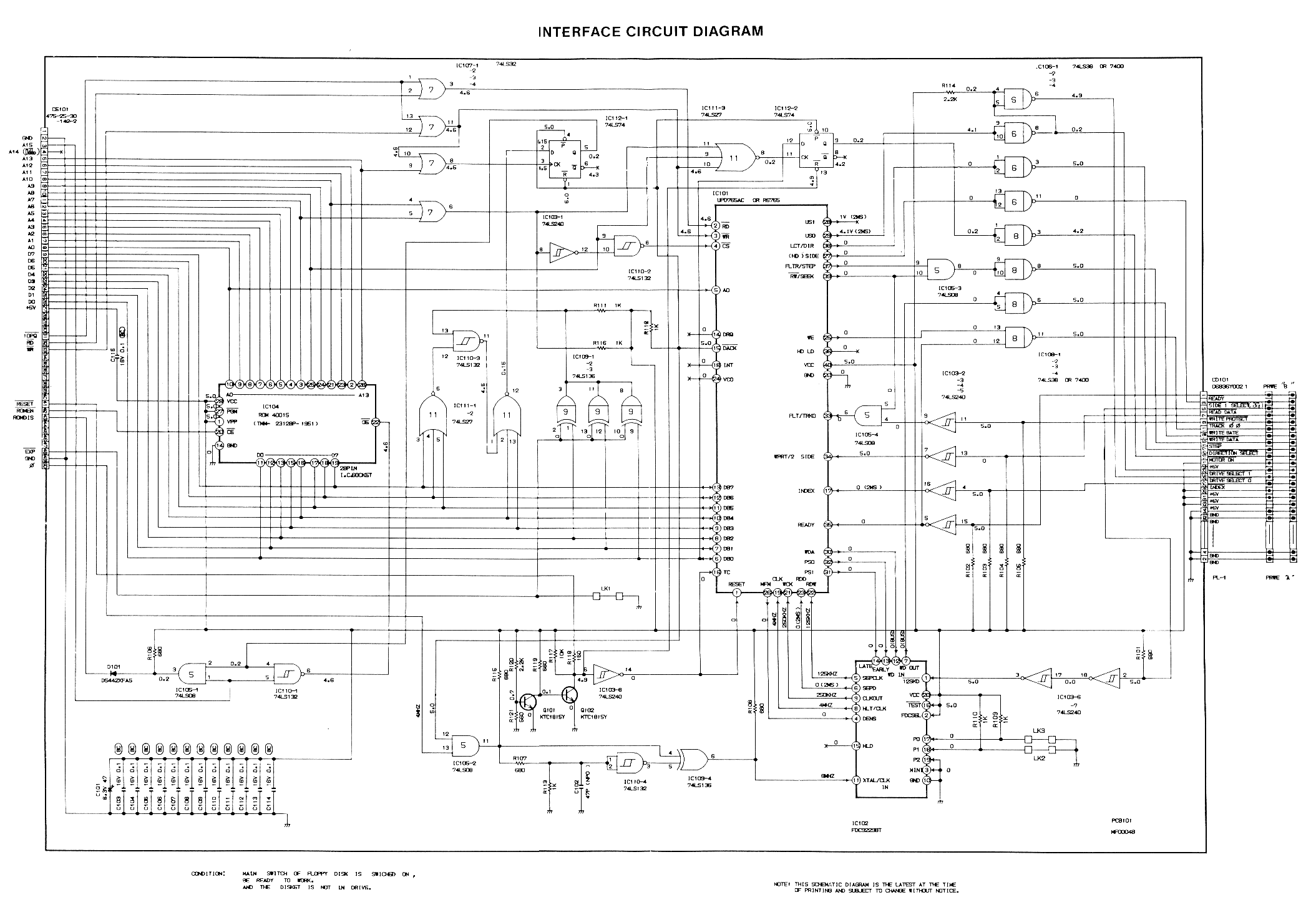
- Media:DDI Schematic.png - DDI-1 Schematic (disc interface for CPC464)
- Media:Panasonic-3 inch Floppy Drive EME-150.pdf Panasonic EME-150M 3inch Floppy Disk Drive Datasheet
- Media:NEC_FD1035_Floppy.pdf - NEC FD1035 3.5inch Floppy Disk Drive Datasheet (1984)