The Digiblaster is a small hardware device plugged into the CPC's printer port to play 8-bit mono sound samples. It was designed by Face Hugger and printed in the German magazine CPC Amstrad International in issue 8-9/1991. In 1995(?) Joshua made a redesign for better sound quality. Bryce made a redesign with even better sound quality.
Software supporting the Digiblaster
Demos
- Bordelik Demo 4 (1995)
- Digital Orgasm (by Prodatron) (1994)
- Meg Ryan Sample (by TFM of FutureSoft)
- Start Trek Sample (by TFM of FutureSoft)
Utilities
- Cocoon Player (by One) (1995)
- Digitracker (by Prodatron) (1993)
- The Drumming CPC (by Andreas Stroiczek, aka Face Hugger) - published as a listing in issue 4/5'92 of CPC Amstrad International, and on the DATABOX cassette/disc for that issue
- FuturePlayer (by TFM of FutureSoft)
- Protracker (by Crown) (1993)
DigiBlaster V2
- Soundplayer pictures (a Digiblaster based card by Futurs')
DigiBlaster V3
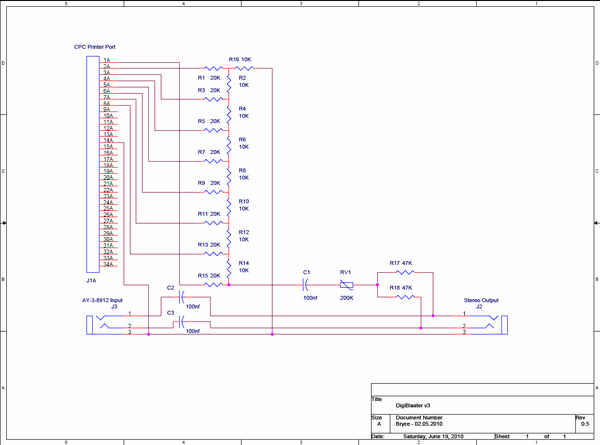
The main difference with this version of DigiBlaster is the additional Line-in connector which allows the user to feed the AY output through the card so that both sound sources are played through the same speakers. The DigiBlaster has been made dual-mono so that both speakers play the sample as is done with the AY-3-8912 Channel B. The variable resistor RV1 adjusts the Digiblasters output level to balance it to the AY level. Unlike V1 + 2, which can be used with a passive mono speaker, the output of V3 has been brought down to Line-out levels and so should be connected to active stereo speakers.
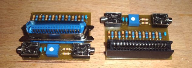
The diodes in the original version have been removed, because they served no meaningful purpose and an R2R ladder design was used for the DA conversion. This not only improves the linearity of the DAC greatly, but also ensures that the output impedance remains stable and of course means not having to buy 8 or 9 different non-standard value resistors. Pin 14 has also been chosen as ground instead of pin 9 to make it compatible with printer ports that have been converted to 8-Bit. The completed devices look like this:
Track layouts have been made for both Centronics and Edge-connector. As seen in the picture above, the layouts use isolation displacement connectors (the type usually intended for flat cable) which have been modified (ie: the plastic band and clips removed) so that it can be mounted directly to the PCB. 1.5mm FR4 PCB should be used preferably to give the circuit stability.
Resources
File:DB3 Edge Layout.pdf - PCB Track Layout for Edge Connector Version
File:DB3 Cent Layout.pdf - PCB Track Layout for Centronics Connector Version


