(→FDC Block Diagram) |
(→Datasheets) |
||
| (75 intermediate revisions by the same user not shown) | |||
| Line 1: | Line 1: | ||
| − | µPD765 - Floppy Disc Controller (used in [[DDI-1]] | + | µPD765 - Floppy Disc Controller (used in CPC 664, CPC 6128, 6128 Plus and [[DDI-1]] expansion). |
| − | + | Besides the Amstrad CPC, this chip equipped the [[PCW|Amstrad PCW]], the [[ZX Spectrum|ZX Spectrum +3]], the [[SC-3000|Sega SC-3000]], and the [[PC|IBM PC]] (including [[Amstrad PC]]). | |
| − | + | The recommended ports used by Amstrad and compatible interfaces are: | |
| − | + | ||
| − | + | ||
| − | + | {| class="wikitable" | |
| + | |- | ||
| + | !I/O port address | ||
| + | !Function | ||
| + | |- | ||
| + | |&FA7E||Floppy Motor On/Off Flipflop | ||
| + | |- | ||
| + | |&FB7E||FDC 765 Main Status Register (read only) | ||
| + | |- | ||
| + | |&FB7F||FDC 765 Data Register (read/write) | ||
| + | |} | ||
| − | + | Note: Bit b10 of the address port is reset as the FDC is seen as an expansion, even if it is an internal chip. Bit b7 is reset to select the FDC. Bits b8 and b0 are used to select the specific mode of operation. All other bits should be set to 1 to avoid conflict. [https://www.cpc-power.com/cpcarchives/index.php?page=articles&num=48 Source] | |
| − | + | Note2: The [[Vortex Disc Drives|Vortex disc interface]] uses other ports. See its dedicated wiki page. | |
| − | + | <br> | |
| − | + | == Motor On/Off Flip-Flop == | |
| + | Writing 00h to Port &FA7E turns all disk drive motors off, writing 01h turns all motors on. It is not possible to turn on/off the motor of a specific drive separately. | ||
| − | + | An exception are the Vortex F1-S, F1-D, M1-S and M1-D drives. (How are they different?) | |
| − | + | ||
| − | + | ||
| − | + | ||
| − | + | ||
| − | + | Another exception is the Gotek drives. They don't take the motor flip-flop into account and are always on. [https://64nops.wordpress.com/2021/07/04/a-la-decouverte-du-fdc/ Source] | |
| − | + | Some FDC commands don't require the motor to be on. For example, the seek or recalibrate commands, that move the floppy drive head, work fine with the motor off. And seek/recalibrate also work with an empty drive (ie. without a floppy disk inserted). [https://64nops.wordpress.com/2021/07/10/a-la-decouverte-du-fdc-episode-2/ Source] | |
| − | + | ||
| − | The | + | The floppy disk rotates at a nominal speed of 300rpm, with some tolerance. This tolerance of the FDC has been measured by [[Roudoudou]] to be ±12% (it worked from 220 kbits/s to 283 kbits/s for a reference of 250 kbits/s). [https://64nops.wordpress.com/2021/09/02/a-la-decouverte-du-fdc-episode-4/ Source] |
| − | + | The FDC speed is more impressive when you realize the Amstrad CPC’s tape loads at only 2 kbits/s in fast mode. Note: tape loading can be way faster than that if an MP3 player is used instead of a real physical tape, as it has been demonstrated here: https://youtu.be/MAIsOIwgJWA | |
<br> | <br> | ||
| Line 36: | Line 40: | ||
== Accessing the FDC 765 == | == Accessing the FDC 765 == | ||
| − | The Main Status Register | + | The Main Status Register signalizes when the FDC is ready to send/receive the next byte through the Data Register. |
| − | The Data Register | + | The Data Register is used to write Commands and Parameters, to read/write data bytes, and to receive result bytes. These 3 operations are: |
| − | + | * Command Phase: A command consists of a command byte (eventually including the MT, MF, SK bits), and up to 8 parameter bytes. | |
| − | + | ||
| − | + | ||
| − | + | ||
| − | A command consists of a command byte (eventually including the MT, MF, SK bits), and up to 8 parameter bytes. | + | |
| − | + | ||
| − | + | ||
| − | + | ||
| − | + | ||
| − | + | ||
| − | + | ||
| − | + | ||
| − | + | ||
| − | + | ||
| − | + | ||
| − | + | * Execution Phase: During this phase, the actual data is transferred (if any). Usually that are the data bytes for the read/written sector(s), except for the Format Track Command, in that case 4 bytes for each sector are transferred. During data transfers between the FDC and the processor, the FDC must be serviced every 26µs (for MFM mode with CPC timings) or the FDC terminates the FDC command. | |
| − | Returns up to 7 result bytes (depending on the command) that are containing status information. | + | * Result Phase: Returns up to 7 result bytes (depending on the command) that are containing status information. During the result phase, all the result bytes must be read. The FDC will not accept a new command until all the result bytes are read. |
| − | + | Note: The Recalibrate and Seek Track commands do not return result bytes directly. Instead, the program must wait until the Main Status Register signalizes that the command has been completed. And then it must (!) send a Sense Interrupt State command to 'terminate' the Seek/Recalibrate command. | |
<br> | <br> | ||
| − | == The 15 FDC Commands == | + | === The 15 FDC Commands === |
{| | {| | ||
| Line 525: | Line 515: | ||
Abbreviations used: | Abbreviations used: | ||
| − | *N = 2^(n+7) bytes, with N between 0 and 7. For example, N=2 means 512 bytes. There is conflicting info about the meaning of N=8: CPC-Power thinks it means 32768 bytes [https://www.cpc-power.com/SectorView.php?fiche=4225&slot=10&rang=0 Source]. Same for Roudoudou [https://64nops.wordpress.com/2021/09/09/a-la-decouverte-du-fdc-episode-5/ Source]. While | + | *N = 2^(n+7) bytes, with N between 0 and 7. For example, N=2 means 512 bytes. There is conflicting info about the meaning of N=8: CPC-Power thinks it means 32768 bytes [https://www.cpc-power.com/SectorView.php?fiche=4225&slot=10&rang=0 Source]. Same for Roudoudou [https://64nops.wordpress.com/2021/09/09/a-la-decouverte-du-fdc-episode-5/ Source]. While Simon Owen thinks it means N=0 (128 bytes) [https://www.cpcwiki.eu/index.php/Format:DSK_disk_image_file_format Source]. On the Intel 82078 datasheet, it is precised that all values up to 7 are allowable. |
*MT = Multi-track (continue multi-sector function on other head) | *MT = Multi-track (continue multi-sector function on other head) | ||
*MF = MFM mode (1 = Double Density) | *MF = MFM mode (1 = Double Density) | ||
| Line 545: | Line 535: | ||
<br> | <br> | ||
| − | == FDC Status Registers == | + | === FDC Status Registers === |
The Main Status register can always be read through Port &FB7E. The other 4 Status Registers cannot be read directly, instead they are returned through the data register as result bytes in response to specific commands. | The Main Status register can always be read through Port &FB7E. The other 4 Status Registers cannot be read directly, instead they are returned through the data register as result bytes in response to specific commands. | ||
| Line 600: | Line 590: | ||
<br> | <br> | ||
| − | == C, H, R, N values at result phase == | + | === C, H, R, N values at result phase === |
If the processor terminates a read (or write) operation in the FDC, then the ID information in the Result phase is dependent upon the state of the MT bit and EOT byte: | If the processor terminates a read (or write) operation in the FDC, then the ID information in the Result phase is dependent upon the state of the MT bit and EOT byte: | ||
| Line 632: | Line 622: | ||
<br> | <br> | ||
| − | == | + | === Notes === |
| − | + | ||
| − | + | ||
| − | + | ||
| − | + | ||
| − | + | ||
| − | + | ||
| − | + | ||
| − | + | ||
| − | + | ||
| − | + | ||
| − | + | ||
| − | + | ||
| − | + | ||
| − | + | ||
| − | + | ||
Before accessing a disk you should issue a ''recalibrate'' command to the drive to move the head backwards until the ''track zero'' signal from the drive is sensed by the FDC. The FDC will also set its track counter for that drive to zero. | Before accessing a disk you should issue a ''recalibrate'' command to the drive to move the head backwards until the ''track zero'' signal from the drive is sensed by the FDC. The FDC will also set its track counter for that drive to zero. | ||
| Line 788: | Line 763: | ||
AMSDOS files are usually stored with a 128-byte [[AMSDOS Header]] (based on cassette header) but can also be headerless, depending on the contents of the file. Unprotected ASCII files do not have header. | AMSDOS files are usually stored with a 128-byte [[AMSDOS Header]] (based on cassette header) but can also be headerless, depending on the contents of the file. Unprotected ASCII files do not have header. | ||
| − | CP/M files do not have headers. | + | CP/M files do not have AMSDOS headers. |
| + | |||
| + | <br> | ||
| + | |||
| + | === Random File Access === | ||
| + | |||
| + | One of the major computing flaws of the Amstrad CPC machines has been the inability to handle simple Random Access Filing even when equipped with disc drives. The only way random access data handling was possible was if the program was written entirely in CP/M. [https://cpcrulez.fr/applications_bureau-random_accesss_database.htm Source] | ||
| + | |||
| + | Nowadays, files can be random accessed in SymbOS, so you can always set the current file pointer to any position in a file and load any amount of data in one step from this position (in CP/M this is at least possible in 128byte steps, in Unidos also byte-based). [https://www.cpcwiki.eu/forum/games/micro-machine-for-symbos-g9k/msg248806/#msg248806 Source] | ||
<br> | <br> | ||
| Line 797: | Line 780: | ||
RSX programs exist on top of AMSDOS to get up to 208 KB of usable space per side, by using 42 tracks with 10 sectors per track. | RSX programs exist on top of AMSDOS to get up to 208 KB of usable space per side, by using 42 tracks with 10 sectors per track. | ||
| − | + | The problem with that is there is not much gap between sectors anymore, and so the diskette becomes very sensitive to rotation speed. | |
The FDC controller can be used to control 80-tracks and/or double sided drives, though AMSDOS doesn't support such formats. To use 80-track drives and/or dual-head drives, you need to use another CPC DOS instead of AMSDOS. The most popular one is [[ParaDOS]]. It can handle up to 796 KB instead of 178 KB for AMSDOS and it supports 22 different disk file formats, including the three standard AMSDOS ones. | The FDC controller can be used to control 80-tracks and/or double sided drives, though AMSDOS doesn't support such formats. To use 80-track drives and/or dual-head drives, you need to use another CPC DOS instead of AMSDOS. The most popular one is [[ParaDOS]]. It can handle up to 796 KB instead of 178 KB for AMSDOS and it supports 22 different disk file formats, including the three standard AMSDOS ones. | ||
| Line 854: | Line 837: | ||
There is also a special version of ParaDOS, called [[VaraDOS]], that supports the [[Vortex Format]]. | There is also a special version of ParaDOS, called [[VaraDOS]], that supports the [[Vortex Format]]. | ||
| + | |||
| + | [[UniDOS]] goes beyond and supports various mass-storage expansions, but also includes support for AMSDOS/ParaDOS floppy discs and tape. | ||
<br> | <br> | ||
| Line 873: | Line 858: | ||
* In MFM encoding, IDAM and DAM are always preceded by three A1 bytes to help the FDC lock onto the data stream after a gap and accurately read the following datas. This is needed because MFM is more compact and harder to read than earlier encoding methods. | * In MFM encoding, IDAM and DAM are always preceded by three A1 bytes to help the FDC lock onto the data stream after a gap and accurately read the following datas. This is needed because MFM is more compact and harder to read than earlier encoding methods. | ||
* Gaps are necessary to accommodate variations in rotation speed between different drives and avoid overlapping. | * Gaps are necessary to accommodate variations in rotation speed between different drives and avoid overlapping. | ||
| − | |||
| − | |||
<br> | <br> | ||
| Line 1,046: | Line 1,029: | ||
The IBM PC supports 3 standard diskette formats on a 5.25 inch drive: | The IBM PC supports 3 standard diskette formats on a 5.25 inch drive: | ||
* The earliest IBM PCs used single-sided, double density, 40 cylinders, 300 RPM, floppy drives which yield a capacity of 160 KB per side. And MS-DOS 1.0 only supported single-sided floppy drives. | * The earliest IBM PCs used single-sided, double density, 40 cylinders, 300 RPM, floppy drives which yield a capacity of 160 KB per side. And MS-DOS 1.0 only supported single-sided floppy drives. | ||
| − | * Double-sided floppy drives were introduced in the IBM PC in 1982 and are supported in MS-DOS 1.1. They originally had a capacity of 320 KB per diskette. MS-DOS 2.0 extended the capacity to 360 KB with a new disk format. [https://minuszerodegrees.net/5150/early/5150_early.htm Source] | + | * Double-sided floppy drives were introduced in the IBM PC in 1982 and are supported in MS-DOS 1.1. They originally had a capacity of 320 KB per diskette. MS-DOS 2.0 extended the capacity to 360 KB with a new disk format (9 sectors per track instead of 8). [https://minuszerodegrees.net/5150/early/5150_early.htm Source] |
* A new floppy drive was introduced with the PC/AT in 1984. It is double sided, quad density, 80 cylinders, with a total capacity of 1.2 MB. The high density drive rotates at '''360 RPM''', so only 15 sectors can be written on a track instead of 18. | * A new floppy drive was introduced with the PC/AT in 1984. It is double sided, quad density, 80 cylinders, with a total capacity of 1.2 MB. The high density drive rotates at '''360 RPM''', so only 15 sectors can be written on a track instead of 18. | ||
| Line 1,059: | Line 1,042: | ||
== FDD Block Diagram == | == FDD Block Diagram == | ||
[[File:Floppy Disk Drive - Block Diagram.png|700px]] | [[File:Floppy Disk Drive - Block Diagram.png|700px]] | ||
| + | |||
| + | <br> | ||
| + | |||
| + | == Chip Variants == | ||
| + | |||
| + | === IC Models used in CPC === | ||
| + | |||
| + | More than one manufacturer made 765 compatible ICs. These are the ones known to be used in the CPC by looking at pictures of CPC mainboards. All should operate almost identically. | ||
| + | |||
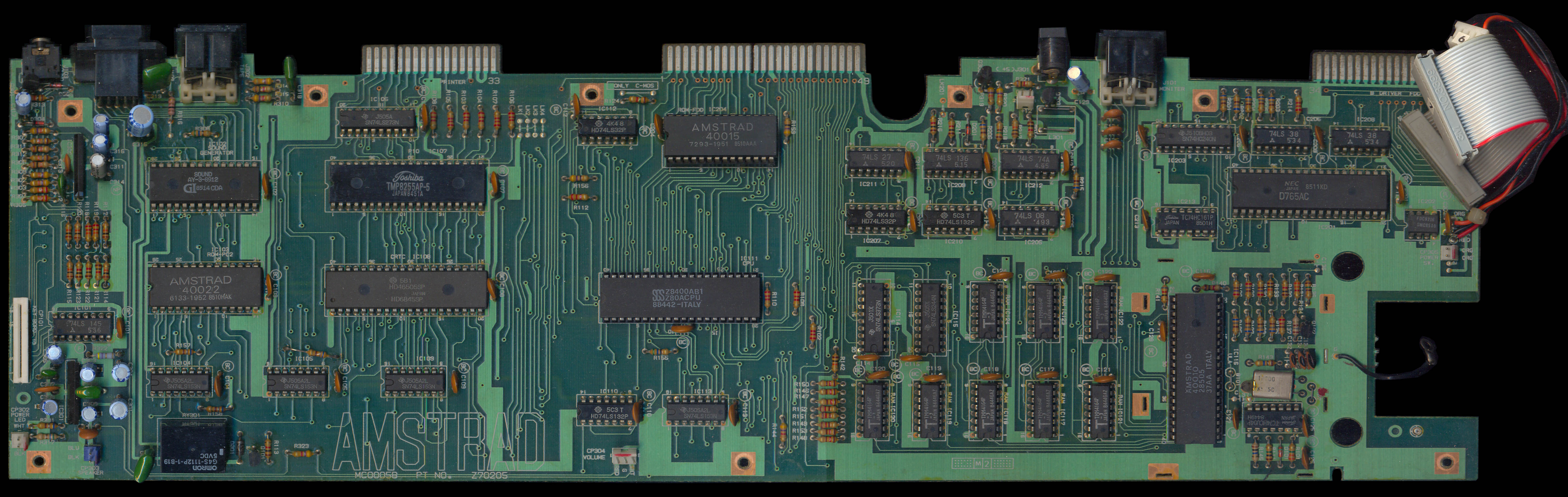
| + | * NEC D765AC [https://www.cpcwiki.eu/imgs/3/3c/CPC664_Z70205_MC0005B_PCB_Top.jpg Source] | ||
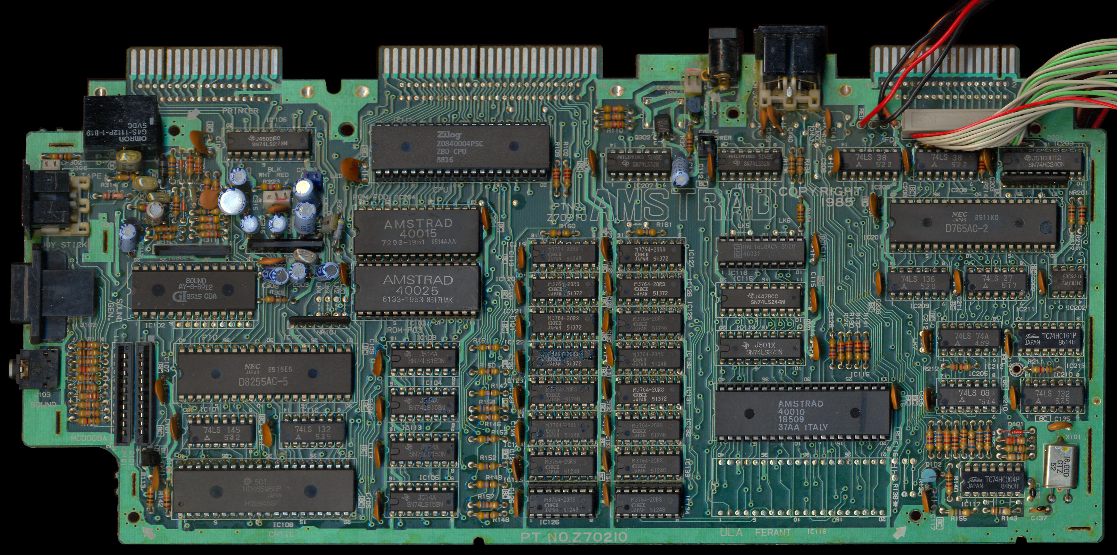
| + | * NEC D765AC-2 [https://www.cpcwiki.eu/imgs/4/45/CPC6128_PCB_Top_%28Z70210_MC0009A%29.jpg Source] | ||
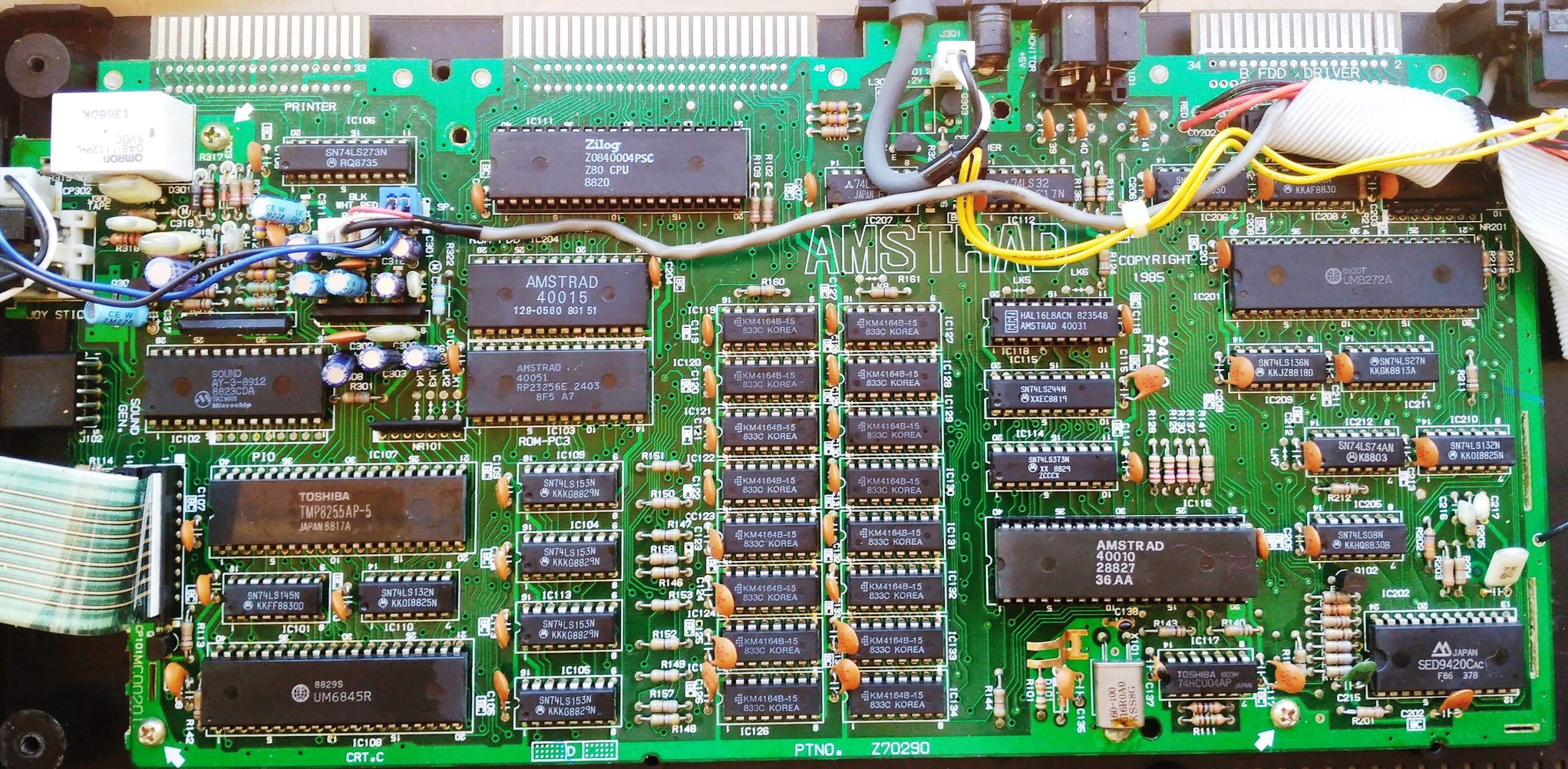
| + | * UMC UM8272A [[Media:Amstrad cpc 6128 azerty (f) placa2.jpg|Source]] | ||
| + | * Zilog Z765APS [https://www.cpcwiki.eu/imgs/f/fb/CPC6128_Z70290_MC0020C_PCB_Top.jpg Source] | ||
| + | * [[Zilog]] Z0765A08PSC [https://www.cpcwiki.eu/imgs/6/67/CPC6128_PCB_Top_%28Z70290_MC0020F%29.jpg Source] | ||
| + | |||
| + | The following data seperators are used: | ||
| + | |||
| + | * FDC9216 [https://www.cpcwiki.eu/imgs/4/45/CPC6128_PCB_Top_%28Z70210_MC0009A%29.jpg Source] | ||
| + | * SED9420C [https://www.cpcwiki.eu/imgs/3/3c/CPC6128_PCB_Top_%28Z70290_MC0020A%29.jpg Source] | ||
| + | |||
| + | The CPC464, CPC472, 464 Plus and GX4000 are not equipped with a FDC chip. | ||
| + | |||
| + | All the floppy disk drive models used by Amstrad are referenced here: [https://www.cpcwiki.eu/index.php/Amstrad_FDD_part Amstrad FDD part] | ||
| + | |||
| + | === Other Variants === | ||
| + | |||
| + | NEC has developed various successors to the original uPD765, such as the uPD72065 (used in the [[Sharp X68000]]), uPD72067, and uPD72069. | ||
| + | |||
| + | Intel has also produced successors of the 8272, such as the 82072, 82077 and 82078. | ||
| + | |||
| + | The КР1810ВГ72А is a Soviet clone of the Intel i8272. It is used in the [[Aleste 520EX]] clone of the Amstrad CPC computer. | ||
| + | |||
| + | The [https://map.grauw.nl/resources/disk/toshiba_tc8566af.pdf Toshiba TC8566AF] is also a variant of the FDC765. | ||
| + | |||
| + | === Competitors === | ||
| + | |||
| + | The main competitor of the µPD765 FDC chip on the market was the WD179x FDC chip family. Its main differences are: | ||
| + | * the 765 has 3 scan commands, while the 179x has none. | ||
| + | * the 765 has 5 status registers, while the 179x only has one. | ||
| + | * the 765 has multi-byte "command phase", while commands are issued to the 179x by writing a single byte to the Command Register, after having set parameters in its dedicated registers. | ||
| + | * the 765 has multi-byte "result phase", while the 179x has none. After a command completes, all the status information is contained in the Status Register as a single byte. | ||
| + | * the 765 has drive select pins to directly select one of four floppy drives, while the 179x has none. Instead, external logic must be used to handle multiple drives. | ||
| + | * the 765 only does standard track formats (preamble, marks and data fields), while the 179x will write anything you tell it in the write track (formatting a track) mode. | ||
| + | |||
| + | Some other computers adopted 3inch floppy disks like Amstrad, but used different FDC chips: | ||
| + | * [[Oric-1/Atmos|Oric]] uses the WD1773 (Jasmin) or WD1793 (Microdisc) FDC chip | ||
| + | * [[Tatung Einstein]] uses the WD1770 FDC chip | ||
| + | |||
| + | Third-party 3inch floppy disk drives (like the Amdek Amdisk) were also available for many systems: Apple II, Atari 8-bit, Tandy CoCo, BBC Micro, etc.. | ||
<br> | <br> | ||
| Line 1,066: | Line 1,098: | ||
* [[Media:UPD765_App_Note_Mar79.pdf| NEC uPD765 Datasheet preliminary (1979)]] [[Media:D765 NEC.pdf]] [[Media:UPD765-NEC.pdf]] [[Media:Z765A datasheet.pdf]] - uPD765 disc controller | * [[Media:UPD765_App_Note_Mar79.pdf| NEC uPD765 Datasheet preliminary (1979)]] [[Media:D765 NEC.pdf]] [[Media:UPD765-NEC.pdf]] [[Media:Z765A datasheet.pdf]] - uPD765 disc controller | ||
* [[Media:Intel 8272A Datasheet preliminary (1982).pdf]] [[Media:Datasheet.hk_d8272a_2873060.pdf|Intel 8272A Datasheet (1986)]] [[Media:Floppy Disk Controller(FDC) UM8272A UM8272A-4.pdf]] - Licensed clone of the uPD765 | * [[Media:Intel 8272A Datasheet preliminary (1982).pdf]] [[Media:Datasheet.hk_d8272a_2873060.pdf|Intel 8272A Datasheet (1986)]] [[Media:Floppy Disk Controller(FDC) UM8272A UM8272A-4.pdf]] - Licensed clone of the uPD765 | ||
| − | |||
* [[Media:TN6-1 9216 Floppy Disk Data Separator Jun82.pdf]] [[Media:FDC9216 datasheet.PDF]] [[Media:SED9420.pdf]] - Data separators | * [[Media:TN6-1 9216 Floppy Disk Data Separator Jun82.pdf]] [[Media:FDC9216 datasheet.PDF]] [[Media:SED9420.pdf]] - Data separators | ||
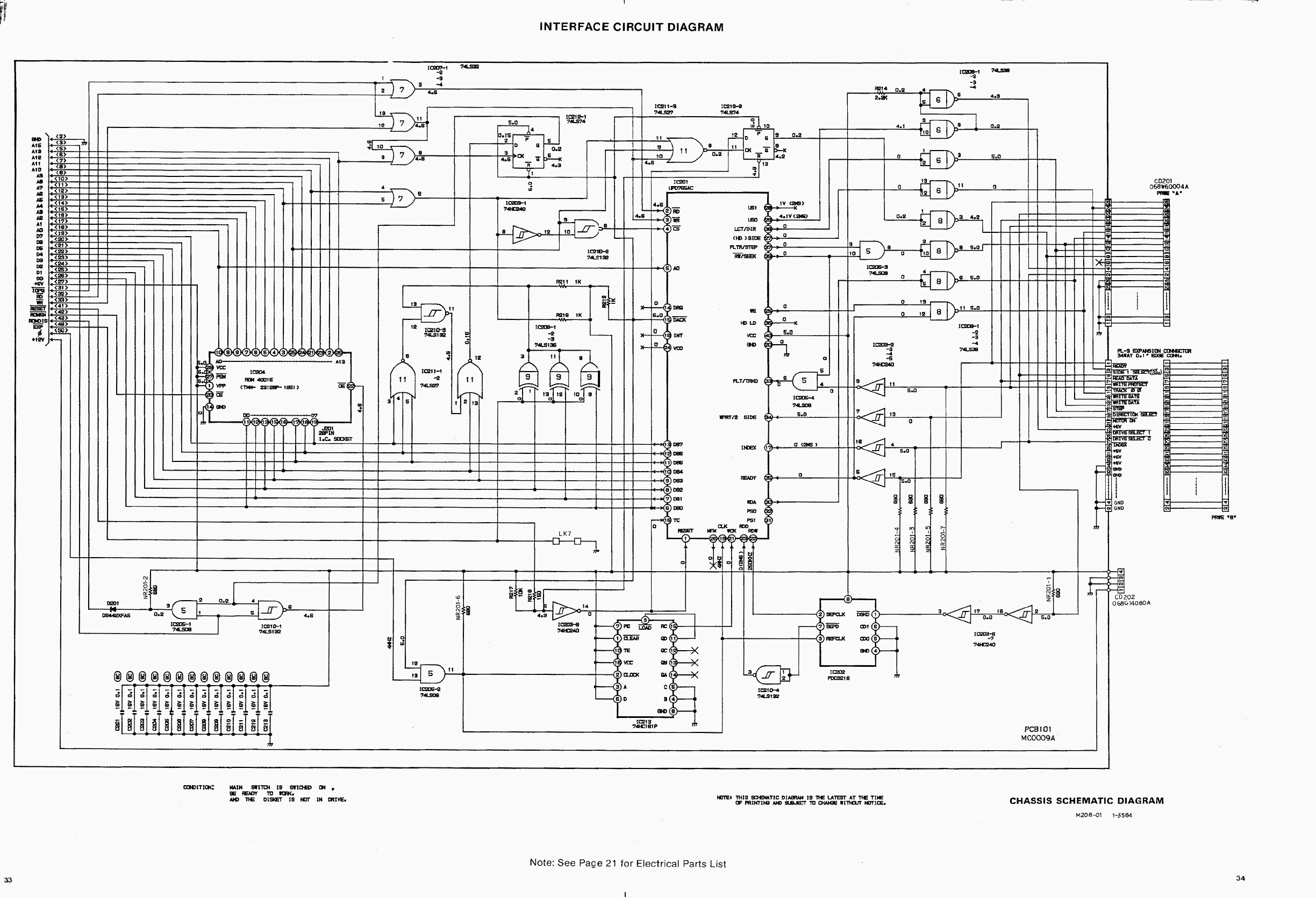
* [[Media:DDI Schematic.png]] - DDI-1 Schematic (disc interface for CPC464) | * [[Media:DDI Schematic.png]] - DDI-1 Schematic (disc interface for CPC464) | ||
| Line 1,077: | Line 1,108: | ||
*[http://quasar.cpcscene.net/doku.php?id=assem:fdc Quasar FDC documentation (in french)] | *[http://quasar.cpcscene.net/doku.php?id=assem:fdc Quasar FDC documentation (in french)] | ||
*[https://64nops.wordpress.com/2021/07/04/a-la-decouverte-du-fdc/ FDC blog articles (in french)] | *[https://64nops.wordpress.com/2021/07/04/a-la-decouverte-du-fdc/ FDC blog articles (in french)] | ||
| + | *[https://en.wikipedia.org/wiki/History_of_the_floppy_disk History of the floppy disk] Wikipedia article | ||
*[https://www.cpc-power.com/cpcarchives/index.php?page=articles&num=92 Floppy disk formats (in french)] | *[https://www.cpc-power.com/cpcarchives/index.php?page=articles&num=92 Floppy disk formats (in french)] | ||
| + | *[https://www.fvempel.nl/3bible.html The 3inch bible] | ||
*[https://info-coach.fr/atari/hardware/FD-Hard.php Atari ST Floppy Drive hardware analysis] | *[https://info-coach.fr/atari/hardware/FD-Hard.php Atari ST Floppy Drive hardware analysis] | ||
*[https://map.grauw.nl/articles/low-level-disk/ MSX low-level disk storage article] | *[https://map.grauw.nl/articles/low-level-disk/ MSX low-level disk storage article] | ||
| + | *[https://youtu.be/aoXr7Anr5DY Réparation de lecteurs Amstrad] [https://youtu.be/-A-USMg9xvE Un Gotek dans un CPC] [https://youtu.be/QPFVfgaMv68 Les disquettes : Le fonctionnement] [https://youtu.be/RMTYevdGH6I Les protections] by [[Rodrik Studio]] | ||
| + | *[https://github.com/dbalsom/fluxfox FluxFox] A floppy disk image library in Rust | ||
| + | |||
| + | <br> | ||
[[Category:CPC Internal Components]][[Category:Programming]][[Category:DATA Storage]][[Category:Electronic Component]] | [[Category:CPC Internal Components]][[Category:Programming]][[Category:DATA Storage]][[Category:Electronic Component]] | ||
Latest revision as of 11:59, 14 May 2025
µPD765 - Floppy Disc Controller (used in CPC 664, CPC 6128, 6128 Plus and DDI-1 expansion).
Besides the Amstrad CPC, this chip equipped the Amstrad PCW, the ZX Spectrum +3, the Sega SC-3000, and the IBM PC (including Amstrad PC).
The recommended ports used by Amstrad and compatible interfaces are:
| I/O port address | Function |
|---|---|
| &FA7E | Floppy Motor On/Off Flipflop |
| &FB7E | FDC 765 Main Status Register (read only) |
| &FB7F | FDC 765 Data Register (read/write) |
Note: Bit b10 of the address port is reset as the FDC is seen as an expansion, even if it is an internal chip. Bit b7 is reset to select the FDC. Bits b8 and b0 are used to select the specific mode of operation. All other bits should be set to 1 to avoid conflict. Source
Note2: The Vortex disc interface uses other ports. See its dedicated wiki page.
Motor On/Off Flip-Flop
Writing 00h to Port &FA7E turns all disk drive motors off, writing 01h turns all motors on. It is not possible to turn on/off the motor of a specific drive separately.
An exception are the Vortex F1-S, F1-D, M1-S and M1-D drives. (How are they different?)
Another exception is the Gotek drives. They don't take the motor flip-flop into account and are always on. Source
Some FDC commands don't require the motor to be on. For example, the seek or recalibrate commands, that move the floppy drive head, work fine with the motor off. And seek/recalibrate also work with an empty drive (ie. without a floppy disk inserted). Source
The floppy disk rotates at a nominal speed of 300rpm, with some tolerance. This tolerance of the FDC has been measured by Roudoudou to be ±12% (it worked from 220 kbits/s to 283 kbits/s for a reference of 250 kbits/s). Source
The FDC speed is more impressive when you realize the Amstrad CPC’s tape loads at only 2 kbits/s in fast mode. Note: tape loading can be way faster than that if an MP3 player is used instead of a real physical tape, as it has been demonstrated here: https://youtu.be/MAIsOIwgJWA
Accessing the FDC 765
The Main Status Register signalizes when the FDC is ready to send/receive the next byte through the Data Register.
The Data Register is used to write Commands and Parameters, to read/write data bytes, and to receive result bytes. These 3 operations are:
- Command Phase: A command consists of a command byte (eventually including the MT, MF, SK bits), and up to 8 parameter bytes.
- Execution Phase: During this phase, the actual data is transferred (if any). Usually that are the data bytes for the read/written sector(s), except for the Format Track Command, in that case 4 bytes for each sector are transferred. During data transfers between the FDC and the processor, the FDC must be serviced every 26µs (for MFM mode with CPC timings) or the FDC terminates the FDC command.
- Result Phase: Returns up to 7 result bytes (depending on the command) that are containing status information. During the result phase, all the result bytes must be read. The FDC will not accept a new command until all the result bytes are read.
Note: The Recalibrate and Seek Track commands do not return result bytes directly. Instead, the program must wait until the Main Status Register signalizes that the command has been completed. And then it must (!) send a Sense Interrupt State command to 'terminate' the Seek/Recalibrate command.
The 15 FDC Commands
|
|
| ||||||||||||||||||||||||||||||||||||||||||||||||||||||||||||||||||||||||||||||||||||||||||||||||||||||||||||||||||||||||||||||||||||||||||||||||||||||||||||||||||||||||||||||||||||||||||||||||||||||||||||||||||||||||||||||||||||||||||||||||||||||||||||||||||||||||||||||||||||||||||||||||||||||||||||||||||||||||||||||||||||||||||||||||||||||||||||||||||||||||||||||||||||||||||||||||||||||||||||||||||||||||||||||||||||||||||||||||||||||||||||||||||||||||||||||||||||||||||||||||||||||
|
|
|
| ||||||||||||||||||||||||||||||||||||||||||||||||||||||||||||||||||||||||||||||||||||||||||||||||||||||||||||||||||||||||||||||||||||||||||||||||||||||||||||||||||||||||||||||||||||||||||||||||||||||||||||||||||||||||||||||||||||||||||||||||||||||||||||||||||||||||||||||||||||||||||||||||||||||||||||||||||||||||||||||||||||||||||||||||||||||||||||||||||||||||||||||||||||||||||||||||||||||||||||||||||||||||||||||||||||||||||||||||||||||||||||||||||||||||||||||||||||||||||||||||||||||||||||||||||||||||||||||||||||||||||||||||||||||||||||||||||||||||||||||||||||||||||||||||||||||||||||||||||||||||||||||||||||||||||||||||||||||||||||||||||||||||
| D7 | D6 | D5 | D4 | D3 | D2 | D1 | D0 | |
|---|---|---|---|---|---|---|---|---|
| command byte 0 | x | MF | x | 0 | 1 | 0 | 1 | 0 |
| command byte 1 | x | HD | US | |||||
| Execution | The first correct ID information on the cylinder is stored in data register | |||||||
| result byte 0 | ST0: status register 0 | |||||||
| result byte 1 | ST1: status register 1 | |||||||
| result byte 2 | ST2: status register 2 | |||||||
| result byte 3 | C: cylinder number | |||||||
| result byte 4 | H: head number | |||||||
| result byte 5 | R: sector number | |||||||
| result byte 6 | N: bytes per sector | |||||||
| D7 | D6 | D5 | D4 | D3 | D2 | D1 | D0 | |
|---|---|---|---|---|---|---|---|---|
| command byte 0 | x | MF | SK | 0 | 0 | 0 | 1 | 0 |
| command byte 1 | x | HD | US | |||||
| command byte 2 | C: cylinder number | |||||||
| command byte 3 | H: head number | |||||||
| command byte 4 | R: sector number | |||||||
| command byte 5 | N: bytes per sector | |||||||
| command byte 6 | EOT: end of track (ie. last sector in track) | |||||||
| command byte 7 | GPL: gap 3 length | |||||||
| command byte 8 | DTL: data length (if command byte 5==0) | |||||||
| Execution | FDC reads all data fields from index hole to EOT | |||||||
| result byte 0 | ST0: status register 0 | |||||||
| result byte 1 | ST1: status register 1 | |||||||
| result byte 2 | ST2: status register 2 | |||||||
| result byte 3 | C: cylinder number | |||||||
| result byte 4 | H: head number | |||||||
| result byte 5 | R: sector number | |||||||
| result byte 6 | N: bytes per sector | |||||||
| D7 | D6 | D5 | D4 | D3 | D2 | D1 | D0 | |
|---|---|---|---|---|---|---|---|---|
| command byte 0 | x | MF | x | 0 | 1 | 1 | 0 | 1 |
| command byte 1 | x | HD | US | |||||
| command byte 2 | N: bytes per sector | |||||||
| command byte 3 | SC: sectors per track | |||||||
| command byte 4 | GPL: gap 3 length | |||||||
| command byte 5 | D: filler pattern to write in each byte | |||||||
| Execution | FDC formats an entire track | |||||||
| result byte 0 | ST0: status register 0 | |||||||
| result byte 1 | ST1: status register 1 | |||||||
| result byte 2 | ST2: status register 2 | |||||||
| result byte 3 | C: cylinder number | |||||||
| result byte 4 | H: head number | |||||||
| result byte 5 | R: sector number | |||||||
| result byte 6 | N: bytes per sector | |||||||
| D7 | D6 | D5 | D4 | D3 | D2 | D1 | D0 | |
|---|---|---|---|---|---|---|---|---|
| command byte 0 | x | 0 | 1 | 1 | 1 | 1 | ||
| command byte 1 | x | HD | US | |||||
| command byte 2 | NCN: new cylinder number | |||||||
| Execution | Head is positioned over proper cylinder | |||||||
| D7 | D6 | D5 | D4 | D3 | D2 | D1 | D0 | |
|---|---|---|---|---|---|---|---|---|
| command byte 0 | x | 0 | 0 | 1 | 1 | 1 | ||
| command byte 1 | x | US | ||||||
| Execution | Head retracted to track 0 | |||||||
| D7 | D6 | D5 | D4 | D3 | D2 | D1 | D0 | |
|---|---|---|---|---|---|---|---|---|
| command byte 0 | x | 0 | 1 | 0 | 0 | 0 | ||
| result byte 0 | ST0: status register 0 | |||||||
| result byte 1 | PCN: present cylinder number | |||||||
| D7 | D6 | D5 | D4 | D3 | D2 | D1 | D0 | |
|---|---|---|---|---|---|---|---|---|
| command byte 0 | x | 0 | 0 | 1 | 0 | 0 | ||
| command byte 1 | x | HD | US | |||||
| result byte 0 | ST3: status register 3 | |||||||
| D7 | D6 | D5 | D4 | D3 | D2 | D1 | D0 | |
|---|---|---|---|---|---|---|---|---|
| command byte 0 | x | 0 | 0 | 0 | 1 | 1 | ||
| command byte 1 | SRT | HUT | ||||||
| command byte 2 | HLT | ND | ||||||
| D7 | D6 | D5 | D4 | D3 | D2 | D1 | D0 | |
|---|---|---|---|---|---|---|---|---|
| command byte 0 | x | Invalid Codes | ||||||
| result byte 0 | ST0: status register 0 | |||||||
Abbreviations used:
- N = 2^(n+7) bytes, with N between 0 and 7. For example, N=2 means 512 bytes. There is conflicting info about the meaning of N=8: CPC-Power thinks it means 32768 bytes Source. Same for Roudoudou Source. While Simon Owen thinks it means N=0 (128 bytes) Source. On the Intel 82078 datasheet, it is precised that all values up to 7 are allowable.
- MT = Multi-track (continue multi-sector function on other head)
- MF = MFM mode (1 = Double Density)
- SK = Skip deleted-data address mark (set if sectors with deleted DAM shall be skipped)
- HD = Head number select
- US = Unit select (drive select)
- HLT = Head Load Time: 2 to 254ms in 2ms increments
- HUT = Head Unload Time: 16 to 240ms in 16ms increments
- SRT = Step Rate Time: 1 to 16ms in 1ms increments (F = 1ms, E = 2ms, etc.)
- ND = Non-DMA mode
Notes:
- Specify: All timings will be doubled on CPC because the FDC runs at 4MHz instead of 8MHz for the datasheet
- Format Track: The processor must supply C, H, R, N to the FDC for each sector during execution phase
- Recalibrate: Walks up to 77 tracks, 80-track drives may need a second recalibrate if failed
- Seek / Recalibrate: All read/write commands will be disabled until successful sense interrupt
FDC Status Registers
The Main Status register can always be read through Port &FB7E. The other 4 Status Registers cannot be read directly, instead they are returned through the data register as result bytes in response to specific commands.
Main Status Register (Port &FB7E):
 b0..3  DB   FDD0..3 Busy (seek/recalib active, until succesful sense intstat)
 b4     CB   FDC Busy (still in command-, execution- or result-phase)
 b5     EXM  Execution Mode (still in execution-phase, non_DMA_only)
 b6     DIO  Data Input/Output (0=CPU->FDC, 1=FDC->CPU) (see b7)
 b7     RQM  Request For Master (1=ready for next byte) (see b6 for direction)
Status Register 0:
 b0,1   US   Unit Select (driveno during interrupt)
 b2     HD   Head Address (head during interrupt)
 b3     NR   Not Ready (drive not ready or non-existing 2nd head selected)
 b4     EC   Equipment Check (drive failure or recalibrate failed (retry))
 b5     SE   Seek End (Set if seek-command completed)
 b6,7   IC   Interrupt Code (0=OK, 1=aborted:readfail/OK if EN, 2=unknown cmd
             or senseint with no int occured, 3=aborted:disc removed etc.)
Status Register 1:
 b0     MA   Missing Address Mark (Sector_ID or DAM not found)
 b1     NW   Not Writeable (tried to write/format disc with wprot_tab=on)
 b2     ND   No Data (Sector_ID not found, CRC fail in ID_field)
 b3,6   0    Not used
 b4     OR   Over Run (CPU too slow in execution-phase (ca. 26us/Byte))
 b5     DE   Data Error (CRC-fail in ID- or Data-Field)
 b7     EN   End of Track (set past most read/write commands) (see IC)
Status Register 2:
 b0     MD   Missing Address Mark in Data Field (DAM not found)
 b1     BC   Bad Cylinder (read/programmed track-ID different and read-ID = FF)
 b2     SN   Scan Not Satisfied (no fitting sector found)
 b3     SH   Scan Equal Hit (equal)
 b4     WC   Wrong Cylinder (read/programmed track-ID different) (see b1)
 b5     DD   Data Error in Data Field (CRC-fail in data-field)
 b6     CM   Control Mark (read/scan command found sector with deleted DAM)
 b7     0    Not Used
Status Register 3:
 b0,1   US   Unit Select (pin 28,29 of FDC)
 b2     HD   Head Address (pin 27 of FDC)
 b3     TS   Two Side (0=yes, 1=no (!))
 b4     T0   Track 0 (on track 0 we are)
 b5     RY   Ready (drive ready signal)
 b6     WP   Write Protected (write protected)
 b7     FT   Fault (if supported: 1=Drive failure)
C, H, R, N values at result phase
If the processor terminates a read (or write) operation in the FDC, then the ID information in the Result phase is dependent upon the state of the MT bit and EOT byte:
| MT | HD | Final Sector Transferred to Processor | ID Information at Result Phase | |||
|---|---|---|---|---|---|---|
| C | H | R | N | |||
| 0 | 0 | Less than EOT | - | - | R + 1 | - |
| 0 | 0 | Equal to EOT | C + 1 | - | 0 | - |
| 0 | 1 | Less than EOT | - | - | R + 1 | - |
| 0 | 1 | Equal to EOT | C + 1 | - | 0 | - |
| 1 | 0 | Less than EOT | - | - | R + 1 | - |
| 1 | 0 | Equal to EOT | - | LSB | 0 | - |
| 1 | 1 | Less than EOT | - | - | R + 1 | - |
| 1 | 1 | Equal to EOT | C + 1 | LSB | 0 | - |
- An empty cell means it is the same value as the one at the beginning of command execution
- LSB (Least Significant Bit): The least significant bit of H is complemented
Notes
Before accessing a disk you should issue a recalibrate command to the drive to move the head backwards until the track zero signal from the drive is sensed by the FDC. The FDC will also set its track counter for that drive to zero.
On an 80-track drive you may need to repeat that twice because some models of the FDC stop after 77 steps so if recalibrating from track 78 or above the controller might not reach track zero.
In order to format, read or write a sector on a specific track you must first seek that track using command 0Fh. That'll move the read/write head to the physical track number. If you don't do that then the FDC will attempt to read/write data from/to the current physical track, irrespective of the specified logical track ID.
The track, sector, and head IDs are logical IDs only. These logical IDs are defined when formatting the disk and aren't required to reflect the physical track, sector, or head numbers. However, when reading or writing a sector you must specify the same IDs that have been used during formatting.
Despite the name, a sector with a Deleted data Address Mark (DAM) is not deleted; the DAM-flag is just another ID bit. 'Deleted' sectors can be read/written just like normal data sectors and if that ID bit is specified correctly in the command.
Standard floppy disk formats
AMSDOS has been designed to complement CP/M, not to compete with it. They share the same structure and can read and write each other's files.
There are 3 standard floppy disk formats in AMSDOS. They are all single-sided and double density (MFM), with the following characteristics:
| DATA | VENDOR or SYSTEM | IBM | |
|---|---|---|---|
| Sector size | N=2 (512 bytes) | ||
| Number of sectors | 9 | 8 | |
| Sector names | &C1 to &C9 | &41 to &49 | &01 to &08 |
| Sector interleave | Yes | No | |
| Formatting byte | &E5 | ||
| Starting track | 00 | ||
| Ending track | 39 | ||
| Catalog position | Track 0: sectors &C1 to &C4 | Track 2: sectors &41 to &44 | Track 1: sectors &01 to &04 |
| Catalog size | 2 KB | ||
| Catalog entries | 64 max | ||
| Size per side | 178 KB | 169 KB | 154 KB |
| Diskette size | 356 KB | 338 KB | 308 KB |
DATA format
It is the most commonly used format on Amstrad CPC as it offers the most available space among the standard formats.
SYSTEM format
The SYSTEM format is a VENDOR format with the addition of information to boot the CP/M on:
- Track 0: sectors &41 (boot sector), &42 (configuration sector), &48, &49
- Track 1: sectors &41, &46, &42, &47, &43, &48, &44, &49, &45
Type |CPM and you will find yourself under CP/M 2.2.
By the way, all the |CPM command does is load the 512 bytes of track 0 sector &41 into memory at address &100 and then execute it.
IBM format
The IBM format is only usable on early IBM PCs as it uses 8 sectors per track and the CP/M filesystem. This was the format used in MS-DOS 1.x. Source
With MS-DOS 2.0 (1983), PC floppies switched to 9 sectors per track and the FAT12 filesystem. Source
And MS-DOS 4.0 (1988) removed compatibility with MS-DOS 1.x formatted floppies. This is one of the reasons why MS-DOS 4.0 faced significant criticism.
Also, CP/M 2.2 supports the IBM format but CP/M Plus does not.
Catalog structure
In CP/M (and AMSDOS), files are stored on disks in a flat structure and can only be organized using USER numbers. CP/M does not have a hierarchical directory structure (with folders and subfolders) like newer operating systems.
The catalog structure supports up to 64 entries of 32 bytes. A file larger than 16KB will require multiple entries in the catalog.
| Byte offset | Description | Comment |
|---|---|---|
| 0 | User Number | USER goes from 0 to 255. USER 229 (&E5) is for deleted files. RSX only gives access to USER 0 to 15. |
| 1-8 | Filename (excluding full stop) | Always in CAPS and maximum 8 characters long. |
| 9-11 | Extension | Always in CAPS and maximum 3 characters long. Read Only flag on byte9 bit7. Hidden flag on byte10 bit7. Archive flag on byte11 bit7. |
| 12 | Current Extent | 0 is first extent. There can be up to 128K bytes (8 logical extents) directly addressed by a single directory entry. Source |
| 13 | Reserved | |
| 14 | Extent High Byte | Not used. |
| 15 | Record Count (Number of 128 Byte Blocks) | Goes up to 128 (&80). |
| 16–31 | Block IDs where to find the file data | 1 byte is used per 1KB block. |
CAT'art
The catalog structure can be hacked by using ascii control characters (codes 0 to 31) to create decorated catalogs (CAT'art).
CAT never loads and executes a boot sector. It just displays the chars of the files using "TXT OUTPUT" (#bb5a) which will execute control codes as well.
There were already tools from the 80ies for modifying a directory in a way that will display colourful chars placed at any location on the screen by adding dummy file entries with 0KB sizes. Or you hardcode it directly by yourself, which allows much more chars and effects.
The trick is to disable text output at the end of a filename to prevent printing file sizes/line feeds and enable it again at the beginning of the next filename; and you also have to use one hidden char for sorting them in the correct order.
See here for more details: All about CAT'arts creation (FR)
CP/M terminology
Record: The basic unit of data access in CP/M, 128 bytes in size. This was the standard size for transferring data between memory and disk.
Block: A group of records, 1 KB in size. Blocks were used to improve disk access efficiency by reading/writing multiple records at once.
Extent: A group of blocks, 16 KB in size. CP/M used extents to manage file allocation, with each extent corresponding to a portion of a file on disk.
Sector: The smallest physically addressable unit on a disk, 512 bytes in size on Amstrad CPC. CP/M accessed the disk at the sector level, though users typically worked with records.
File Headers
Cassette files are divided into 2KB blocks (then subdivided in 256-byte segments + CRC), each block being preceded by a 64-byte header.
AMSDOS files are usually stored with a 128-byte AMSDOS Header (based on cassette header) but can also be headerless, depending on the contents of the file. Unprotected ASCII files do not have header.
CP/M files do not have AMSDOS headers.
Random File Access
One of the major computing flaws of the Amstrad CPC machines has been the inability to handle simple Random Access Filing even when equipped with disc drives. The only way random access data handling was possible was if the program was written entirely in CP/M. Source
Nowadays, files can be random accessed in SymbOS, so you can always set the current file pointer to any position in a file and load any amount of data in one step from this position (in CP/M this is at least possible in 128byte steps, in Unidos also byte-based). Source
Custom floppy disk formats
Usually single sided 40-track 3" disk drives are used in CPCs. For practical purposes, 42 tracks could be used — the limit is specific to the drive and some support more tracks but 42 is a good maximum.
RSX programs exist on top of AMSDOS to get up to 208 KB of usable space per side, by using 42 tracks with 10 sectors per track. The problem with that is there is not much gap between sectors anymore, and so the diskette becomes very sensitive to rotation speed.
The FDC controller can be used to control 80-tracks and/or double sided drives, though AMSDOS doesn't support such formats. To use 80-track drives and/or dual-head drives, you need to use another CPC DOS instead of AMSDOS. The most popular one is ParaDOS. It can handle up to 796 KB instead of 178 KB for AMSDOS and it supports 22 different disk file formats, including the three standard AMSDOS ones.
| Format | Capacity | Catalog | Type | Sectors/Track | Sectors |
|---|---|---|---|---|---|
| PARADOS 80 | 396k | 128 | SS | 10 | &91-&9a |
| PARADOS 41 | 203k | 64 | SS | 10 | &81-&8a |
| PARADOS 40D | 396k | 128 | DS | 10 | &a1-&aa |
| ROMDOS D1 | 716k | 128 | DS | 9 | &01-&09 |
| ROMDOS D2 | 712k | 256 | DS | 9 | &21-&29 |
| ROMDOS D10 | 796k | 128 | DS | 10 | &11-&1a |
| ROMDOS D20 | 792k | 256 | DS | 10 | &31-&3a |
| ROMDOS D40 | 396k | 128 | SS | 10 | &51-&5a |
| S-DOS | 396k | 128 | SS | 10 | &71-&7a |
| DATA (SS 40) | 178k | 64 | SS | 9 | &c1-&c9 |
| DATA (DS 40) | 356k | 64 | DS | 9 | &c1-&c9 E |
| DATA (SS 80) | 356k | 64 | SS | 9 | &c1-&c9 E |
| DATA (DS 80) | 716k | 64 | DS | 9 | &c1-&c9 E |
| SYSTEM (SS 40) | 169k | 64 | SS | 9 | &41-&49 |
| SYSTEM (DS 40) | 346k | 64 | DS | 9 | &41-&49 E |
| SYSTEM (SS 80) | 346k | 64 | SS | 9 | &41-&49 E |
| SYSTEM (DS 80) | 704k | 64 | DS | 9 | &41-&49 E |
| IBM (SS 40) | 169k | 64 | SS | 8 | &01-&08 |
| IBM (DS 40) | 346k | 64 | DS | 8 | &01-&08 E |
| IBM (SS 80) | 346k | 64 | SS | 8 | &01-&08 E |
| IBM (DS 80) | 704k | 64 | DS | 8 | &01-&08 E |
| ULTRAFORM | 203k | 64 | SS | 9 | &10-&19 |
Legend: SS = Single-Sided, DS = Double-Sided.
Half of the original AMSDOS rom is occupied by Dr. Logo from Digital Research. If you replace AMSDOS with ParaDOS, you will lose access to Dr. Logo.
There is also a special version of ParaDOS, called VaraDOS, that supports the Vortex Format.
UniDOS goes beyond and supports various mass-storage expansions, but also includes support for AMSDOS/ParaDOS floppy discs and tape.
FDC Track Format
The 765 FDC only supports the single-density IBM 3740 track format and the double-density IBM System/34 track format, which are the defacto standards for floppy disks in most computer systems. These formats have been created by an IBM engineer named Alan Shugart (not to be confused with Amstrad's CEO, Alan Sugar).

On Amstrad CPC, the MFM MODE pin of the FDC is not connected. So the FM mode is unusable.
On Amstrad CPC, an MFM track contains about 6250 raw bytes: 200 ms per track (at 300rpm) / 32 µs per byte (with a bit cell of 4µs). Fun fact: You can squeeze a few more bytes on disk by using a floppy drive that spins a little slower, and counting on the tolerance of the FDC to make that disk readable on unmodified floppy drives.
Notes:
- IAM signifies the beginning of a track.
- IDAM marks the beginning of a sector's header.
- DAM (or DDAM) marks the beginning of the actual data in a sector. Deleted data sectors are marked by an F8 byte instead of an FB byte.
- In MFM encoding, IDAM and DAM are always preceded by three A1 bytes to help the FDC lock onto the data stream after a gap and accurately read the following datas. This is needed because MFM is more compact and harder to read than earlier encoding methods.
- Gaps are necessary to accommodate variations in rotation speed between different drives and avoid overlapping.
Gaps Protection
Gaps was a common method of protecting floppy disks against copying on the Amstrad CPC, particularly with French software houses such as Infogrames and Loriciels. It consists of writing specific values (other than the standard &4E) in the separation area between 2 consecutive sectors.
When the protected program is launched, it checks if these special values (most often a string signature) are present. If they aren't, the program can then crash or reset the computer or format the disk – or in the case of some games, the player can play the game, but it will crash or freeze at some point.
The trick is that the 765 FDC can read the custom byte values in the gaps, but it cannot write them. This made it hard for people to make working copies of protected disks.
Weak Sectors Protection
Another common copy-protection scheme was using (fully or partially) unmagnetized sectors. The unmagnetized data would then appear as random values when read by the FDC.
When the protected program is launched, it reads these weak sectors multiple times. Due to their unstable nature, these sectors will return different data on each read. If the program detects this changing data, it recognizes the disk as an original and continues to run. If not, the program can then crash, reset the computer, etc.
The trick is that the FDC cannot unmagnetize portions of a sector or leave portions of a sector unmagnetized to recreate this effect on another floppy disk.
Error Detection
The FDC765 happens to use the exact same algorithm for error detection as the one the Amstrad firmware uses to check each 256-byte tape segments.
The CRC error-detecting code is initialised to &FFFF. It is updated byte by byte and uses the CCITT-CRC16 algorithm. It is written after the ID and data fields of each sector in big-endian format (high byte first and then low byte).
FM Encoding
FM (Frequency Modulation) encoding was one of the earliest methods used to store data on floppy disks by creating changes in the magnetic field, known as flux transitions, to represent binary data.
In FM encoding, each bit of data is divided into two distinct parts: a clock signal and a data signal. The clock signal is always present to indicate the timing, while the data signal only appears when the bit is a 1, and remains absent when the bit is a 0.
This constant clock pulse ensures that the FDC always knows where each bit begins and ends. For every bit of information written to the disk, there’s always one clock signal and, if the data is a 1, a data signal as well.

Legend: C=Clock, D=Data
MFM Encoding
MFM (Modified Frequency Modulation) was developed as a more efficient alternative to FM encoding. This method greatly reduces the number of transitions needed to represent data compared to FM.
If a cell contains a 1, the signal will be recorded in the middle of the cell. If a cell contains a 0, the signal will be recorded at the beginning of the cell, unless it was preceeded by a cell with a 1. If a signal is transmitted for a 0 cell, it is used as clock signal.
This clever encoding eliminates the need for separate clock signals for every bit, as they are implied by the data pattern. It allows the recording of double the density compared to FM without increasing the bit rate on the floppy material. Each bit cell has only half the size compared to FM.

HD Floppy Disks on CPC
It is theoretically possible to use HD floppy disks (1.44MB) on CPC by using either a Gotek drive or Amiga HD floppy drives spinning at 150rpm. However, nobody has ever written a CPC DOS to make use of it.
On a real floppy drive, if you want to fit more sectors on the same track, you have 2 options: you can make the FDC run faster, or you can make the disk spin slower.
Normally, HD disks use a faster FDC (with an automatic switch between the slow and fast modes).
But, for example on Amiga systems with HD drives, they used floppy drives that spin slower for HD disks (150 rotations per minutes instead of 300) and this allow to use the same controller as before. By the time the floppy has done one complete rotation, you can write 18 sectors instead of just 9.
With a real PC HD floppy drive, this requires some mechanical modifications, and you may get into trouble if the spinning speed is not fast enough.
But with the Gotek, this is not a problem. You can have as many sectors as you want, and the Gotek will generate the index pulse (simulating the floppy completing a turn) after it has sent them all. So it is essentially emulating a floppy that turns very slowly. The FDC has no problems handling that, but you may need to be a bit more relaxed than usual with the timeouts, as it will be some time before the sector you need will pass in front of the drive head, and the index pulse will also be slower than usual.
On a Gotek drive, you can even simulate fantasy floppy disks with up to 255 cylinders, and the FDC will handle them perfectly fine.
Mass Storage via FDC
The Gotek drive (with a FlashFloppy or HxC firmware) has a special direct access mode that allows it to be used as a poor's man hard drive, offering access to up to 32 GB of storage space. It is accessible via the track 255. Source
This is a great feature as it alleviates the need for another mass storage expansion. And the relative slowness of this solution (~15 KB/s) compared to a proper mass storage device (~130 KB/s with Symbiface II) is not much of an issue on Amstrad CPC.
This special Gotek direct access mode is supported in SymbOS. Source
FDC Block Diagram
The FDC chip is quite different from the other CPC chips. It contains its own internal CPU, ROM and RAM.

Internal details of the chip
Internally this is a microcoded part with a primative controller of NEC’s own design.
Testing microcode embedded in a part can be troublesome. The uPD765 had a few extra gates associated with the DMA Request and DMA Ack pins.
Presenting a certain illegal combination here places the part into a “test” mode and allows the sequencer microcode to be output on the normal Data pins. The sequencer microcode is responsible for high level commands such as Read Track, Recalibrate, Format Track, or Write Data.
There is a similar test mode for the nano-code array which serializes data at the floppy disk head. Source
Intel 8272 FDC
NEC uPD765 (or just D765) is exactly the same chip as the 8272. NEC and Intel cross-licensed a bunch of IP back in the day. Source
The 8272/µPD765 was the result of a cross-licensing deal between NEC and Intel. It was essentially NEC design. Source
The decapped photos of Intel 8271, NEC D765 and Intel 8272 chips prove that NEC D765 and Intel 8272 chips are identical.
Generic System Diagram
The Amstrad CPC and Amstrad Plus do not have a DMA controller associated with the FDC. And the clock runs at 4MHz instead of 8MHz.

Unconnected Pins
The DRQ (14), INT (18), VCO SYNC (24), MFM MODE (26), US1 (28), and HEAD LOAD (36) pins are not connected. The TC (16) and RESET (1) pins are connected together. Source
At the end of a successful read or write command, the program should send a Terminal Count (TC) signal to the FDC. However, in the CPC the TC pin isn't connected to the I/O bus, making it impossible for the program to confirm a correct operation. For that reason, the FDC will assume that the command has failed, and it'll return both Bit 6 in Status Register 0 and Bit 7 in Status Register 1 set. The program should ignore this error message.
The CPC doesn't support floppy DMA transfers, and the FDC's Interrupt signal isn't used in the CPC.
The FDC controller inside the CPC or in the Amstrad DDI-1 expansion doesn't have the US1 pin connected. This means it can only select floppy drives 0 and 1, and not drives 2 and 3. And AMSDOS supports a maximum of two disk drives only.
However, the FDC in the Vortex disc interface does have the US1 pin connected, and so it can manage up to 4 floppy drives.
ABBA switch
The ABBA switch is a common hardware modification that allows users to swap between Drive A and Drive B.
On Amstrad CPC, some games and other software were designed to run specifically from Drive A, creating a problem when the disk you needed was in Drive B.
The ABBA switch resolved this issue by allowing you to "swap" the designation of the two drives. When the switch is activated, Drive A becomes Drive B, and vice versa, effectively swapping their roles.
PC to CPC floppy connector

Ready / Disk Changed signal
This signal differs between floppy drives model:
- For 3inch floppy drives, it is a "Ready" signal (pin 26). The /RDY signal turns on when a disk is inserted and spinning in the drive, usually after detecting 2 or 3 index pulses, depending on the drive model. It turns off immediately if the disk is removed or the motor stops.
- For PC 3.5inch floppy drives, it is a "Disk Changed" signal (pin 34). The /DSKCHG signal determines whether the same disk loaded during the previous disk access is still in the drive.
The easiest solution to this issue is to force the Ready signal on the cable. However, the CPC will hang if you type the CAT command with no disk inserted (inserting a disk will unblock it).
Alternatively, you can Modify PC floppy drives to create a Ready signal, or use Amiga floppy drives, which already have this signal.
Gotek drives with FlashFloppy or HxC firmware can also be configured to simulate the Ready signal. Don't forget to use a proper floppy drive cable then, not the one commonly sold by CPC hobbyists with the Ready signal forced.
PC Floppy Drive types
The IBM PC supports 3 standard diskette formats on a 5.25 inch drive:
- The earliest IBM PCs used single-sided, double density, 40 cylinders, 300 RPM, floppy drives which yield a capacity of 160 KB per side. And MS-DOS 1.0 only supported single-sided floppy drives.
- Double-sided floppy drives were introduced in the IBM PC in 1982 and are supported in MS-DOS 1.1. They originally had a capacity of 320 KB per diskette. MS-DOS 2.0 extended the capacity to 360 KB with a new disk format (9 sectors per track instead of 8). Source
- A new floppy drive was introduced with the PC/AT in 1984. It is double sided, quad density, 80 cylinders, with a total capacity of 1.2 MB. The high density drive rotates at 360 RPM, so only 15 sectors can be written on a track instead of 18.
The IBM PS/2 introduced two standard 3.5 inch diskette formats:
- The first is a double sided, double density, 80 cylinders, format yielding a capacity of 720KB. The double density drive rotates at 300 RPM.
- The other is double sided, quad density, 80 cylinders, with a total capacity of 1.44 MB. The high density drive rotates at 300 RPM.
Fun fact: The original IBM PC didn’t have a hard drive, even as an option. And MS-DOS 1.x didn't have any support for hard drives either. Hard drives only became a thing with the introduction of the IBM PC/XT and MS-DOS 2.0 in 1983. But the floppy drive was not the only option to load programs on the original IBM PC. You could also use a tape deck, just like on Amstrad CPC. However, the tape port disappeared with the PC/XT. Source
FDD Block Diagram

Chip Variants
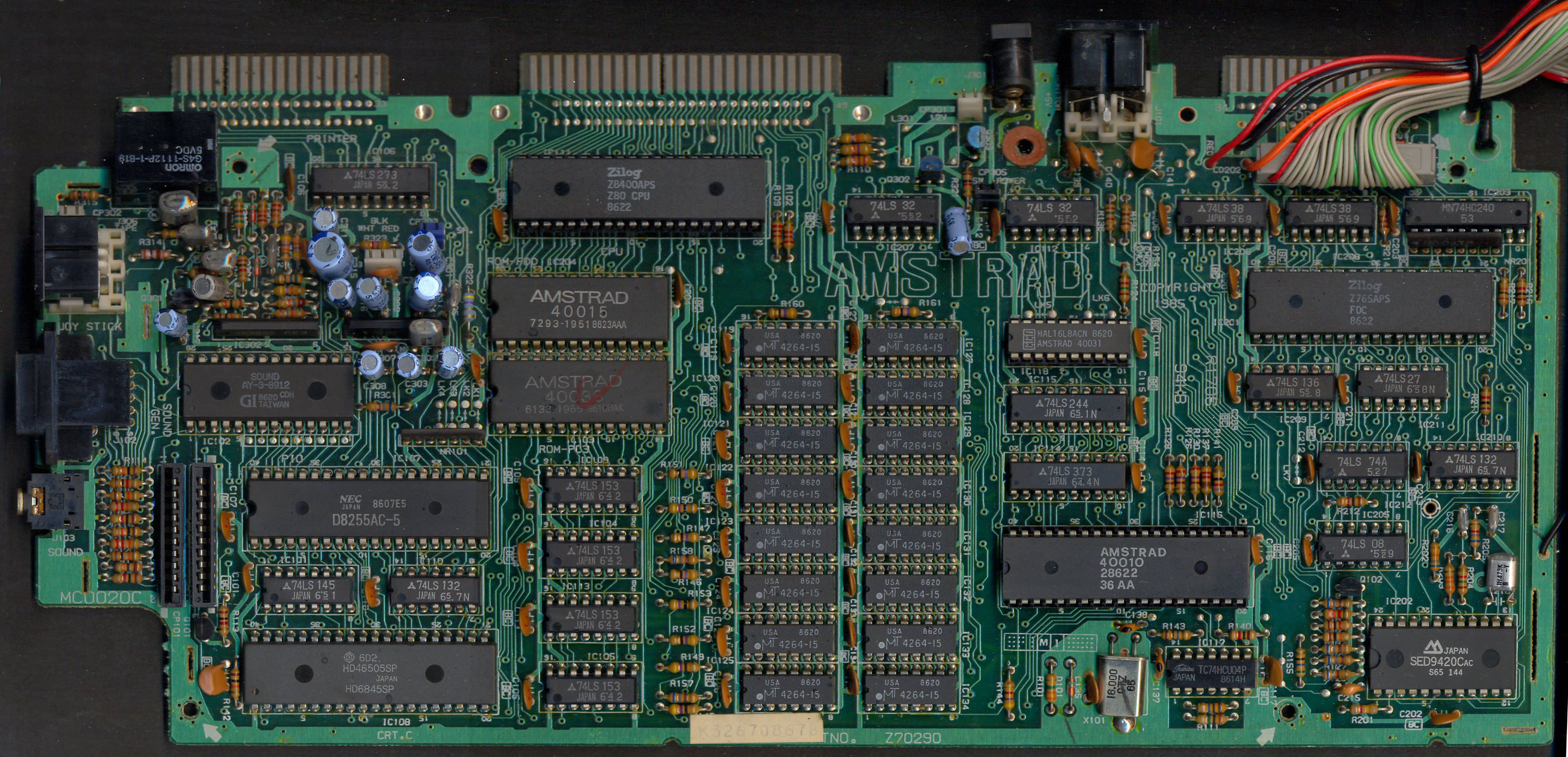
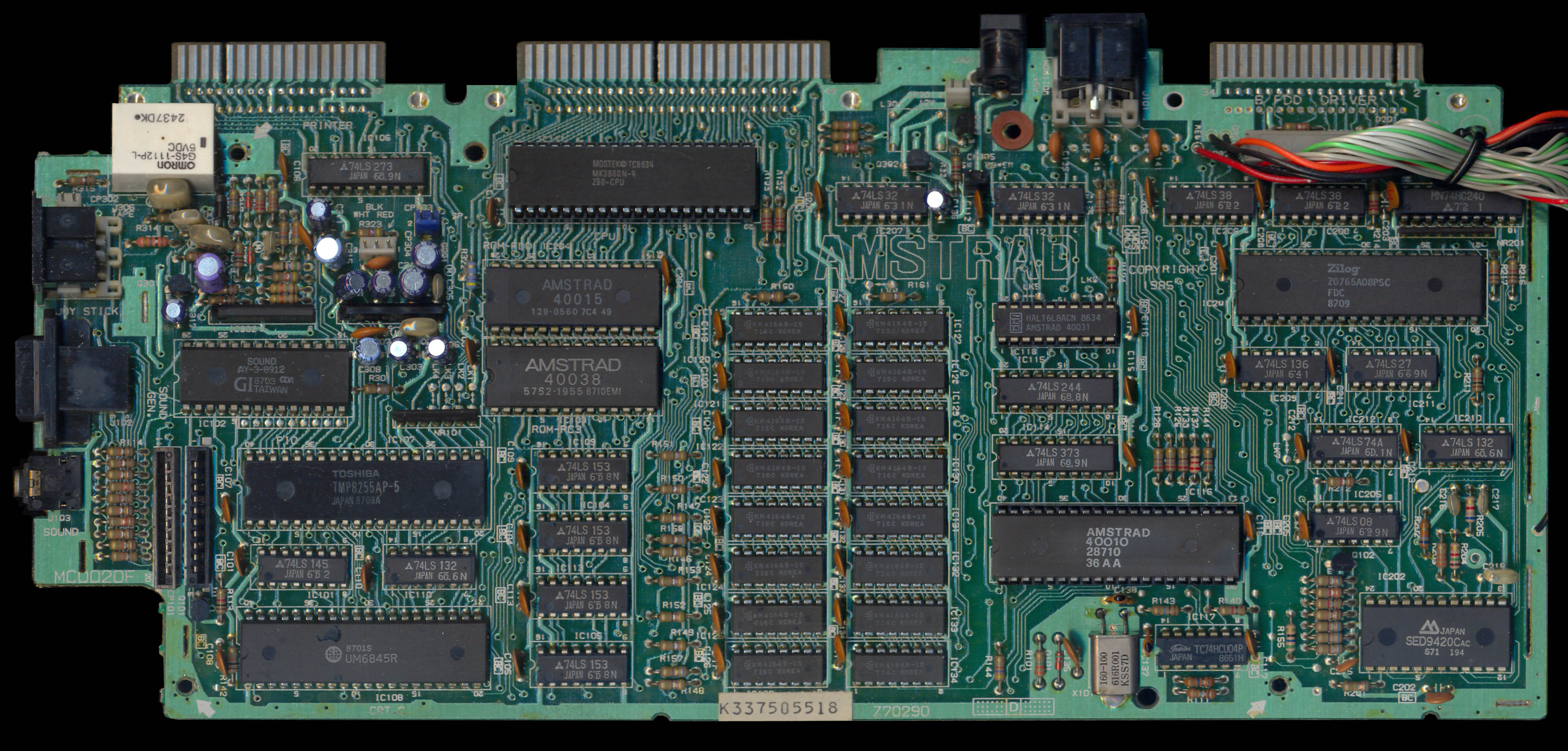
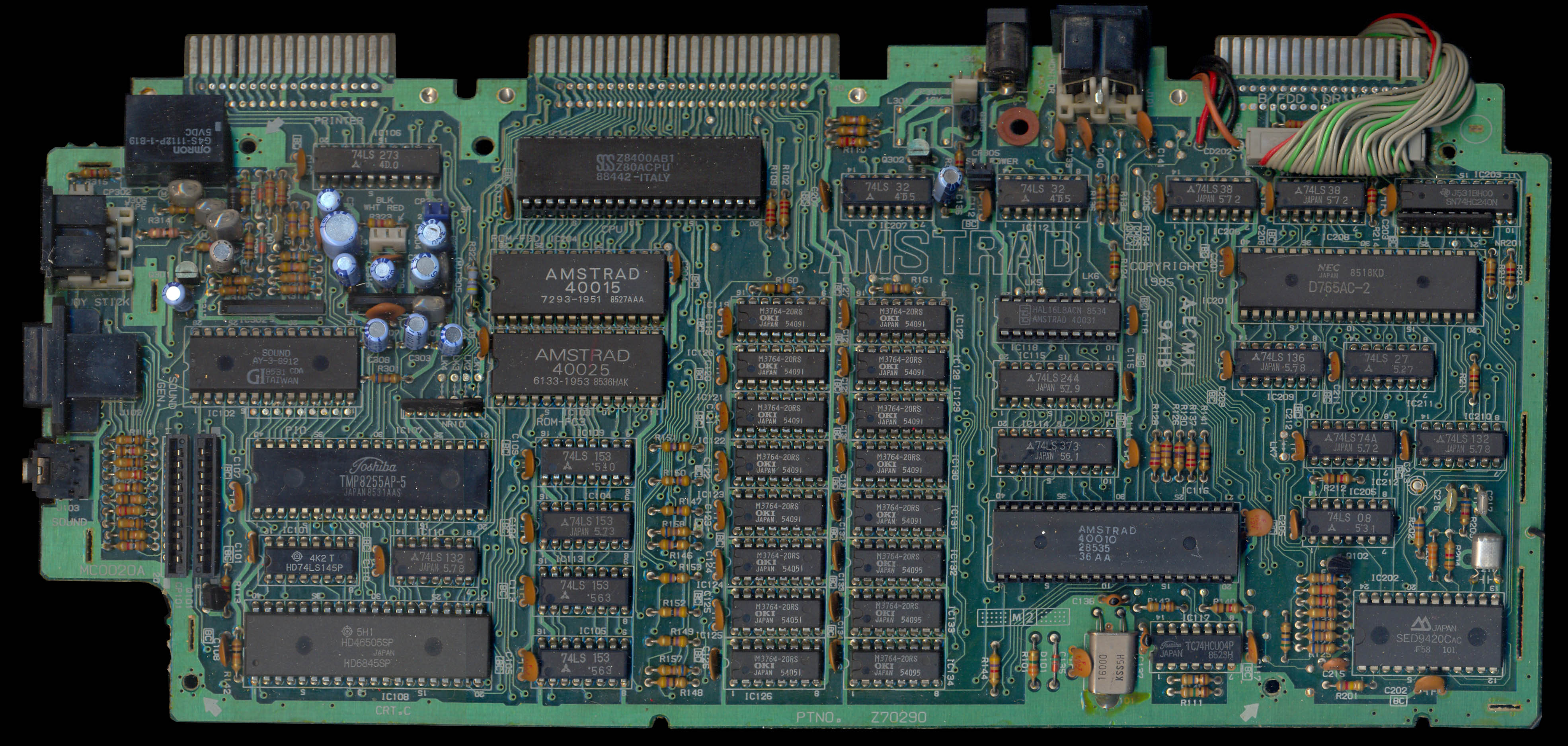
IC Models used in CPC
More than one manufacturer made 765 compatible ICs. These are the ones known to be used in the CPC by looking at pictures of CPC mainboards. All should operate almost identically.
- NEC D765AC Source
- NEC D765AC-2 Source
- UMC UM8272A Source
- Zilog Z765APS Source
- Zilog Z0765A08PSC Source
The following data seperators are used:
The CPC464, CPC472, 464 Plus and GX4000 are not equipped with a FDC chip.
All the floppy disk drive models used by Amstrad are referenced here: Amstrad FDD part
Other Variants
NEC has developed various successors to the original uPD765, such as the uPD72065 (used in the Sharp X68000), uPD72067, and uPD72069.
Intel has also produced successors of the 8272, such as the 82072, 82077 and 82078.
The КР1810ВГ72А is a Soviet clone of the Intel i8272. It is used in the Aleste 520EX clone of the Amstrad CPC computer.
The Toshiba TC8566AF is also a variant of the FDC765.
Competitors
The main competitor of the µPD765 FDC chip on the market was the WD179x FDC chip family. Its main differences are:
- the 765 has 3 scan commands, while the 179x has none.
- the 765 has 5 status registers, while the 179x only has one.
- the 765 has multi-byte "command phase", while commands are issued to the 179x by writing a single byte to the Command Register, after having set parameters in its dedicated registers.
- the 765 has multi-byte "result phase", while the 179x has none. After a command completes, all the status information is contained in the Status Register as a single byte.
- the 765 has drive select pins to directly select one of four floppy drives, while the 179x has none. Instead, external logic must be used to handle multiple drives.
- the 765 only does standard track formats (preamble, marks and data fields), while the 179x will write anything you tell it in the write track (formatting a track) mode.
Some other computers adopted 3inch floppy disks like Amstrad, but used different FDC chips:
- Oric uses the WD1773 (Jasmin) or WD1793 (Microdisc) FDC chip
- Tatung Einstein uses the WD1770 FDC chip
Third-party 3inch floppy disk drives (like the Amdek Amdisk) were also available for many systems: Apple II, Atari 8-bit, Tandy CoCo, BBC Micro, etc..
Datasheets
- NEC uPD765 Datasheet preliminary (1979) Media:D765 NEC.pdf Media:UPD765-NEC.pdf Media:Z765A datasheet.pdf - uPD765 disc controller
- Media:Intel 8272A Datasheet preliminary (1982).pdf Intel 8272A Datasheet (1986) Media:Floppy Disk Controller(FDC) UM8272A UM8272A-4.pdf - Licensed clone of the uPD765
- Media:TN6-1 9216 Floppy Disk Data Separator Jun82.pdf Media:FDC9216 datasheet.PDF Media:SED9420.pdf - Data separators
- Media:DDI Schematic.png - DDI-1 Schematic (disc interface for CPC464)
- Media:Panasonic-3 inch Floppy Drive EME-150.pdf Media:NEC_FD1035_Floppy.pdf - Floppy disk drives
- Media:Floppy User Guide.pdf - Floppy User Guide
External links
- Quasar FDC documentation (in french)
- FDC blog articles (in french)
- History of the floppy disk Wikipedia article
- Floppy disk formats (in french)
- The 3inch bible
- Atari ST Floppy Drive hardware analysis
- MSX low-level disk storage article
- Réparation de lecteurs Amstrad Un Gotek dans un CPC Les disquettes : Le fonctionnement Les protections by Rodrik Studio
- FluxFox A floppy disk image library in Rust