About the uIDE project
The uIDE concept is not terribly new (search for GIDE and you will see what I mean, although these adapters are not available any more).
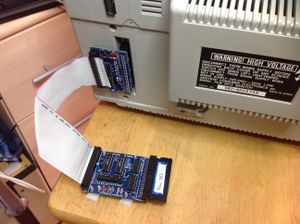
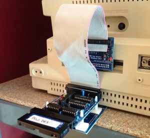
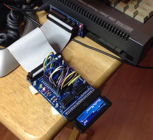
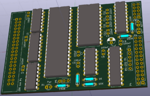
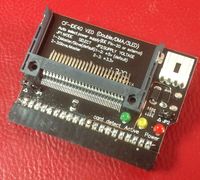
The idea was to produce a low cost IDE adapter, suitable for connecting to Z-80 computers via a shim board that fits between a (socketed) Z-80 and its main board socket. From the shim, a 40 way IDC cable is connected to the uIDE adapter board, then a CF card or DOM plugs into the other end (if there is space inside your Z-80 computer, you may be able to connect the shim and uIDE cards directly together without a cable). uIDE cards are "universal" because their I/O base address is fully configurable via a row of 2 position jumpers on the board.
Once the hardware is installed, drivers need to be written (see below).
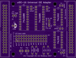
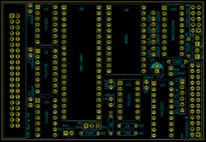
uIDE-16 can be configured for use on any Z-80 microcomputer such as the CPC range of computers. It is called "uIDE-16" because it decodes all 16 address bus lines to provide access to the IDE ATA registers as is required by the Amstrad CPC machines, yet it has an 8-bit addressing mode so that it can be used with other (more normal) Z-80 machines that only use the lower 8 bits of the address bus for I/O addressing. In this mode, some components (U1 and its socket and decoupling capacitor, C1) may be left off the board.
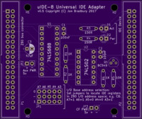
uIDE-8 is a similar design that just decodes the low 8 bits of the Z-80 adddress bus, and this can be used on the PCW and most other Z80 machines but not on the CPC machines. uIDE-16 has a user-configurable 8-bit mode that allows it to work with 8-bit addressed I/O as well. However, uIDE-8 is slightly smaller and cheaper than uIDE-16.
Project status
All boards are in production.
Superbrain QD drivers now available.
Feature list
- Compact design, only 4 ICs (uIDE-16) or 2 ICs (uIDE-8) and a smattering of discrete components. Board measures 79x60mm (uIDE-16).
- Implemented using cheap, readily available parts (7400-series ICs only, plus some capacitors, resistors and LEDs).
- Can be connected to the PCW expansion port (see below) or internally via a Z80 shim card (note, this requires a socketed Z80).
- Does not require a separate 5v power supply (the computer supplies power).
- Can supply 5v to an attached CF card adapter if necessary. Also supplies +5v via IDE Pin 20, although not all devices use it (hence the additional supply option).
- Driver supports Amstrad PCW CP/M Plus only at this time (it is implemented as a FID).
- A separate driver exists for Lifeboat CP/M 2.2 on the TRS-80 Model II that can be ported on demand to other CP/M 2.2 variants.
- Intertec Superbrain QD now fully supported.
- The CP/M driver runs the IDE device in LBA / 8 bit mode, so DOMs or CF cards are recommended (at least 128MB is recommended).
- Fully programmable I/O address decoding (via on-board jumpers). Initial I/O range (uIDE-16, for the as yet unwritten CPC driver) is FEF0-FEF7 and (uIDE-8, for the PCW driver) is C8-CF, but you can change this to suit your own hardware / driver.
- Can be used on any other Z80 computer with a socketed processor.
- Implements a standard bus connector that exactly matches the Z80 pinout.
Limitations
- The driver implements a CP/M format on the IDE device, so it is not directly readable on a PC using the Windows File Manager. However, you can use Win32DiskImager to get a copy of the entire disk, then cpmtools to extract files or put them back onto the disk image (see below).
- uIDE may not be compatible with certain types of IDE device (CF cards, DOMs).
- There is no driver support for IDE CD drives.
- I have not provided driver support for uIDE-16 on the CPC 6128. However, please see the HDCPM thread
- Any IDE device connected to uIDE should support IDE-ATA 8-bit data transfer mode. If you connect a device which only supports 16-bit mode, you may find it is incompatible or has half the expected space available (this is because in ATA 16 bit transfer mode, the interface only uses 8 of the possible 16 transfer bits).
- IDE devices must also support LBA (logical block addressing) mode (for my drivers).
- Expect this list to be expanded as more questions are asked!
Downloads
Here is a list of download files that are discussed on this page, in one place for convenience.
| File | Description | Wiki page section link |
|---|---|---|
| File:All board BOM 2.csv | Bill of Materials for self builders. Includes all boards. | BOMs |
| File:UIDE-PCW.zip | ZIP file containing uIDE disk image and utilities for the PCW. Release 1.11 | uIDE disk image and utilities download |
| http://www.cpcwiki.eu/index.php/File:Xdriver_PCW_suite_0.1.zip | Zip file containing uIDE utilities and the PCW driver FID file. You don't need this if you are using the uIDE-PCW.img file. | Drivers |
| http://www.cpcwiki.eu/index.php/File:Xdrv_n.zip | Zip file containing uIDE xdrv.fid v1.11 variants that allocate different numbers of uIDE drives (from 1-12), for use in situations where having many drives slows the PCW down (such as when starting up Locoscript), or you find that CP/M Plus does not have enough memory to support the full compliment of drives, devices and applications you need to run (not a problem I've encountered yet!). | See http://www.cpcwiki.eu/forum/nc100-nc200-pcw-pda600/locoscript-and-fid-files/msg173804 for discussion. |
| http://www.cpcwiki.eu/forum/nc100-nc200-pcw-pda600/announce-pcw-xdriver-suite-v1-11-for-uide-users/ | Announcement thread for the later driver with download and discussion of repair procedure to fix possible problems with the earlier formatter. Use this instead of the v0.1 driver. | Drivers |
| http://www.cpcwiki.eu/forum/nc100-nc200-pcw-pda600/cpm-plus-1-11-1-5-download/?action=dlattach;attach=21897 | ZIP file with later CP/M EMS/EMT files that support PCW FID drivers. | CPM Plus version requirements |
| File:XTEST-6128.zip | uIDE-16 test program for CPC6128. | Testing the IDE device |
| File:IDE SPEC.PDF | IDE Specification document, which is needed for writing IDE drivers. | More information |
| https://drive.google.com/file/d/1HaWvlNjYw6uwRpdOBd-Tokw0SgrVJanO/view?usp=share_link | Intertec Superbrain I and II QD uIDE driver v0.12 package |
Z80 Shims
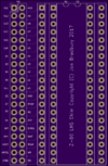
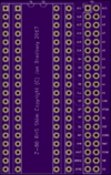
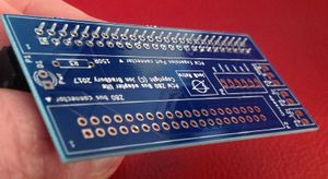
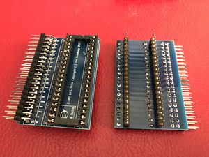
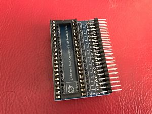
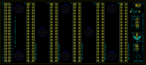
These small cards are inserted between the Z80 and its socket, and present all 40 pins of the CPU via a 40 way header. This header is the "Z80 Bus" that the uIDE cards connect to.
Choose the one that fits best inside your machine. A CPC6128 needs the left hand shim if you want to fit the uIDE card internally, although space is very tight under the keyboard (the processor sits directly behind the expansion port). You may also fit the RHS shim to a 6128, on the following provisos:
- a) the strain relief bar of the Z80 bus cable that plugs into the shim must be removed (otherwise it fouls the rear case).
- b) the Z80 bus cable might not be able to bend round to allow internal fitting and
- c) the Z80 bus cable, when passed out of the expansion port slot, may get in the way of any expansion you have fitted (and it may not, depends on the shape of the expansion unit.
PCW 8000 machines require the LHS shim, because the RHS shim fouls the inside of the case. The good news here is that you can pass the Z80 bus cable through the case at the right hand rear corner (where the keyboard cable plug is) without modifications to the case. If you look closely at the join, you can see there's a short section of case, right on the corner, that has a flat face. Route the cable through this section, and don't tighten the screw on that corner up too hard.
Important: Check your machine has a socketed Z80 before ordering a shim (you should open it up anyway to decide which shim gives the best mounting solution). If the Z80 does not have a socket and you are not willing to desolder the Z80 and fit a socket to the machine, then a shim is not the solution for you.
Machine-specific expansion port adapters
Use one of these cards if you prefer to connect your uIDE card to the machine's expansion port rather than via its Z80 socket.
PCW 8256/8512/9512
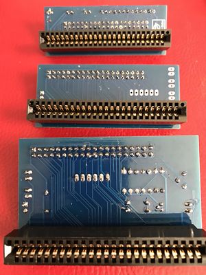
These cards allow connection of a uIDE card to the 50 way expansion port on the back of the machine. They are designed to support the PCW edge connector type port, but the European Centronics type port might be accommodated if a suitable connector exists (50 way Centronics, 2.54 header pitch). In addition they provide access to the PCW's 5v and 12v power supply, as well as other signals from the card edge connector. One variant has a small composite video circuit so that you can connect an external monitor to the PCW.
Schneider PCW variants
You can connect uIDE-8 to a Schneider PCW expansion plug using a 50 way Centronics to 50 way IDC cable.
You also need a modified PCW expansion port adapter card, with a 50 way IDC header installed instead of the 50 way edge connector. The Schneider cable plugs into this, and you then connect the uIDE to it in the usual fashion.
CPC 6128
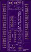
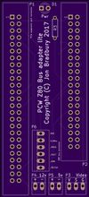
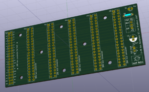
The CPC 6128 bus adapter is a card which plugs directly into the 6128's expansion port with the front face of the board facing away from the CPC. The image shows an early render from OSH Park. Per the other adapter cards, uIDE plugs into it via a 40 way IDC cable.
BOMs
For self assemblers, I drew up a parts list broken down by board with Farnell order numbers. I recommend you shop round for these parts, after seeing what they look like on Farnell. Also, you have options where there are alternatives shown. In particular, with the edge and IDC connectors, consider how you wish to mount and connect the boards and select the connector appropriately. The exapansion interfaces are designed to have an edge connector soldered to the back of the board, so that it sits over the slot with the components facing away from you (if you are sitting in front of the computer), but if you choose to use a 50 way IDC connector (with cable to expansion port) then you can mount it on the component side of the board.
Connectivity options
Here is a table summarising your options for connecting a uIDE device to your computer.
Choose one option from each column. Some guidance notes:
- Expansion adapters connect to the rear edge connector of your PCW or 6128. Choose one if you don't want to fit the uIDE internally or your Z80 is not socketed.
- Z80 shims are for general purpose use and will fit any Z80 machine with a socketed processor. Choose LHS or RHS dependant on the space and orientation of the CPU in your machine.
- Direct connection (between the host adapter and uIDE device) means soldering the Z80 bus header pins on each board directly together. Note, some combinations may prevent this, or may require odd orientation of the two cards.
- The IDE device can plug directly into the uIDE board. Angled IDC connectors are recommended when building the board.
- A DOM is recommended as it is the only device I have tested the uIDE prototype with. Unfortunately, I can't guarantee that specific Compact Flash cards will be compatible but if you let me know what works and what doesn't we can build a compatibility list on this page.
- uIDE-8 cannot be used on the CPC6128 as it uses 16 bit I/O addressing. Choose uIDE-16.
Special notes for uRTC-8 users
- You can connect uRTC-8 to your computer by choosing any two options from the first two columns.
- uRTC-8 cannot be used on the CPC6128 as it uses 16 bit I/O addressing.
Information for self builders
Assembly advice
I have written this section with the inexperienced electronic hobbyist in mind. If you are a hot shot with a soldering iron, please don't be offended!
Assembly is fairly straightforward, you just need to watch the orientation of the connectors (check twice before soldering) and polarised components (LEDs and electrolytic capacitor). The boards all have silk screen printed component pads with names and values showing, so it is very difficult to get it wrong. Read this section before proceeding, and if in doubt, ask on the forum.
Order of assembly
The general order of assembly of uIDE boards is to fit the shortest components first, because it makes handling the board easier if you are laying it on a flat surface to solder:-
- Solder in the resistors, LEDs (watch the orientation, see below), 100nf capacitors (the tiny ones).
- Fit the pin headers (JP1, JP2, etc, making sure they are upright. I use an IDC plug for this and solder one pin, then adjust, then solder in all the other pins).
- Next fit the IC sockets, matching the orientation of the notch against the outline on the board.
- Fit the Z80 bus and IDE sockets (making sure they are square). Check the orientation of Pin 1 before soldering and note that, if you use a boxed header, the cutout should align with the cutout on the board outline, or face the same way as Pin 1 of the footprint. Examine the pictures and if in doubt, ask.
- The last thing to fit is the 47uF capacitor (C5), because it is the tallest component (watch the orientation, see below).
- Apply any fixes required to the board (see below).
- Fit the jumper plugs according to the board configuration section below.
The adapter board assembly order is not so critical. I usually fit the 50 way edge connector first, then clamp it in my bench vise to place the other components.
LEDs and electrolytic capacitor
Be sure that you put the LEDs and electrolytic capacitor in the right way round.
- With LEDs, the shorter leg is the negative end and it goes into the square pad (longer leg into the round pad).
- Electrolytic caps are the same, they have a long leg (positive) and a short leg (negative, often marked with a - sign or black bar on the side of the capacitor can). Match the positive leg with the pad that is marked with a + sign on the PCB.
Z80 Shims
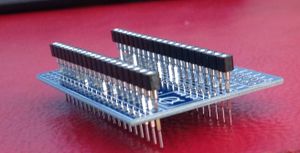
When building a z80 shim, choose a set of header pins for the legs you are plugging into the Z80 socket on the computer's motherboard that are thin (do not use the the standard type otherwise the Z80 socket will be damaged). Take a look at the pictures of the shims to see what I mean. Solder these headers in first, because the Z80 socket you solder to the shim probably won't let you get access to the pin header once fitted. Make sure they are straight - I use a small IDC connector plugged into the pins and clamped in a vise to hold them straight during soldering, like this:
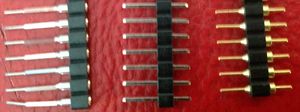
The pin headers shown below are the main options when building a Z80 shim.
- The one to the right is the optimal choice, it has gold plated pins with a circular cross section having a diameter of about .45mm. The shorter end is soldered into the pad on the shim board from the underside. This pin design gives more clearance on the top side of the board for you to fit a low profile IC socket, saving height. I use these when building shims for other people.
- The middle one is a "standard" pin header with a square cross section and width of about .65mm. Avoid like the plague, as it will damage the main board socket.
- The left hand one is a sort of combined pin and socket with an acceptable diameter end. It looks tall but as it includes the socket pins it makes the shim easier to build.
Here is a picture of the left hand one in situ. The Z80 sits a bit higher than the first option.
On the shim's bus connector footprint, pin 1 is labelled "A11" and has a square pad (all the others are round). Use an unboxed 40 way right angled pin header for this, as shown in the photos on this page, or you may find space is too tight inside the computer, and check the orientation of the header and cable is correct before soldering the header in. The header should be fitted to the top side of the board, as shown in the shim pictures.
uIDE-16 fix for 8-bit mode
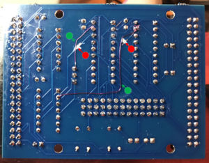
The current version of uIDE-16 (v0.3) has some errors that prevent the 8-bit addressing mode from working. If you want to use it in 8-bit addressing mode, some modifications are required as shown below.
On the underside of the board:
- Cut the tracks marked with a red disk.
- Add the links marked with a green disk.
Please note, for the CPC6128 you use 16-bit addressing mode, and these modifications are unnecessary.
uIDE-8 "red" boards
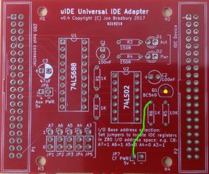
The uIDE-8 red boards are a previous version of the blue boards and have some minor problems which can be corrected easily.
- The CF_PWR connector has no +5v, due to a pair of missing vias. To fix, insert a link wire as shown in the picture in green. However, you may not need this as certain devices like DOMs can take power from pin 20 of the IDE connector.
- The through holes for the transistor Q1 (shown with a yellow dot) are tight. You may need to drill them out and this will remove the via, so apply solder on both sides of the PCB around Q1's legs. Alternatively, you can surface mount the transistor by bending its legs into feet and standing it on the pads, then carefully solder them. A bit fiddly, but will work.
- The I/O address jumpers are upside down compared to the blue boards. Set the address with reference to the 1 and 0 as printed on the red PCB, not as photoed on this page (the address is the same).
PCW Expansion port adapter video circuit fix
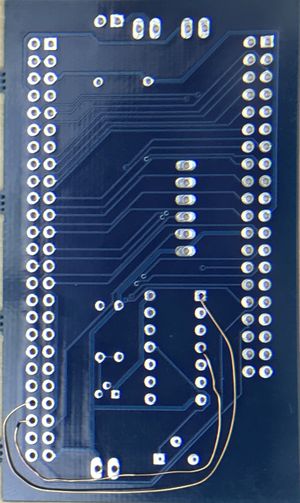
Due to an error in the schematic capture, the video circuit on the PCW Expansion port adapter isn't actually connected to the PCW. The fix is straightforward and involves putting in a couple of jumper wires as follows:
- Connect Expansion port connector Pin 44 to U1 pin 1
- Connect Expansion port connector Pin 46 to U1 pin 4
If you use copper wire such as you find on a transformer or prototyping wire, you can connect these pads before assembling the expansion port connector and U1's socket. It's best to lay these on the underside of the board:
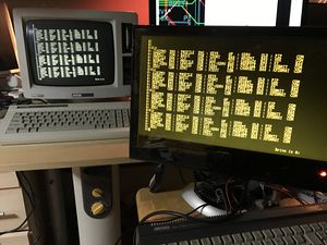
And once fixed, the video circuit works nicely, giving a good clean signal:
You may find it necessary to adjust the trimmer to get a signal. When assembling, set the trimmer about half way to begin with, then adjust it in situ until the best picture is obtained.
PCW Expansion port adapter composite video cable
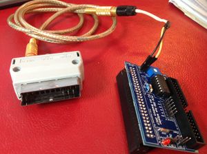
If you want to connect a PCW Expansion port adapter to a display, you're going to need to make up a suitable video cable. The composite video signal is on the pad closest to the trimmer, with the ground pin next to it. This is marked on the board in tiny lettering. If you use a double pin header to populate the video output pads on the PCB (as I do when building them for other people), your cable should look like this:
The wires connected to the PCB are:
- Yellow - Composite Video
- Black - signal ground
I use a female phono plug, cable mounted, connected to the copper shielded cable (standard audio cable, male phono to male phono), which is in turn connected to the Video input of a SCART adapter. This plugs into the back of a TV. Depending on your TV / monitor, you may need a different plug on the end of your cable.
Z80 Bus cable
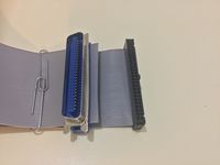
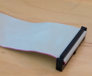
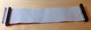
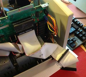
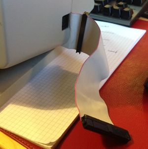
A "Z80 Bus cable" is merely a 40 way IDC ribbon cable with female plugs at either end. You find these in use inside old PCs, connecting the mother board to an IDE hard drive. If you want to make your own, the only thing to be aware of is the orientation of the cable with respect to the locating tab on the plugs. Consider these pictures:
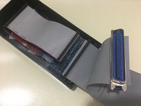
On the left is a typical cable. The red painted wire in the foreground is PIN 1. You can see that the tab is on the left hand side of the plug and this is standard. Now look at the right hand picture. With the plug flipped and the red wire again in the foreground, the tab is on the right hand side. There is also a strain relief bar fitted, which helps prevent the plug from coming apart when being removed from a socket. This turns the ribbon wire 180 degrees, so you can imagine there is room for error when making these cables up. My advice would be to lay out the cable, put the plugs in situ (but don't crimp them yet) and check them against the uIDE and expansion port adapter before completing assembly. For the Z80 shim, you just need to ensure that you can connect pin 1 to the pad marked "A11".
Some more pictures, this time with the strain bar removed and the cable folded out. Study these carefully before making your cable or connecting a ready made IDC cable.
uIDE-8 74LS02 considerations
The timing of the Z80 /RD signal is very tight, so the choice of NOR gate IC that you put at U2 is critical. Choose a fast part such as a 74F02. At least one manufacturer, Misubishi, makes a fast enough 74LS02 and that is what I used in my prototype. It has a propagation delay of 6-15ns, and the typical delay is somewhere in between, say 9ns. This appears to be the lowest speed the design will allow, although I have only tested with a few '02 variants. If in doubt, check the manufacturer's datasheet and don't buy anything with an average propagation delay larger than say 9ns. I've listed the delay times for several different '02 logic chips below. It's quite surprising what the propagation time range is for parts that are supposedly "standard".
Note: In the table, "Likely" means "my best guess based on the published propagation delay times". Avoid anything that is "Not compatible".
74??02 Propagation times
Curiously, I received a new batch of TI SN74LS02s that work with uIDE-8, so perhaps you should try any you have in your parts box first. However, if in doubt, choose a 74F02 or known working type shown above. If you find working types that are not listed, or are shown as not compatible, please let me know so I can update the list.
As a result of this investigation, the BOM was updated to specify a 74F02 for U2.
PCW and 6128 Expansion Port 50 way edge connector
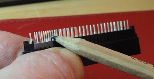
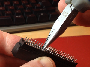
I made a mistake with the row spacing on the boards so it will be necessary to bend the two pin rows inwards so they nearly touch, then bend them out about 1/2 way down each leg with needle nose pliers. Really sorry about that. But it's reasonably easy to do if you're careful.
I posted this picture on the forum, and I hope it illustrates the point.
The rows on the PCB are 2.54mm apart, which is fine if you want to fit a 50 way box header and use a 50 way IDC connector to 50 way IDC edge connector cable, but not fine for fitting this type of edge connector. Hence a little bit of hackery being necessary when fitting the edge connector directly to the adapter board.
I found when building a board for someone that it is easier to leave one row of pins straight, and use needle pliers to bend the other row's pins into a sort of Z shape. Here's how to do it.
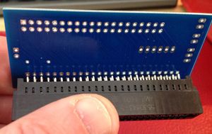
Also, please note that the edge connector must be fitted so that it comes out of the back of the board. Please check the pictures of the finished boards and ensure you get this right. If in doubt, contact me.
Pictures of the built boards
I present here some photos of the finished boards for reference. Click on an image for a closer look.
Notes
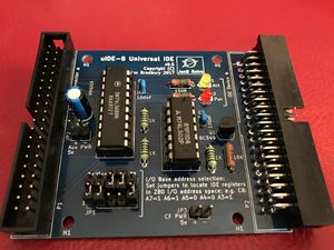
- uIDE-8 is configured for the PCW driver's I/O address. Note the jumper settings.
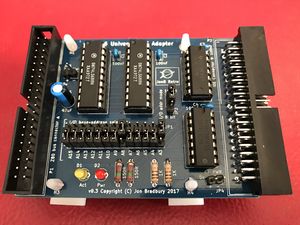
- uIDE-16 is configured for the proposed 6128 driver's I/O address, and is set for 16-bit mode, Again, note the jumper settings.
- If you are building uIDE for a specific machine, you can solder links in place rather than fit header pins and jumper shunts to save money. However, ensure the address configuration is correct before soldering the links!
- The expansion port pictures show (front to back, respectively) the PCW video adapter, PCW "lite" adapter, 6128 adapter.
I/O Address configuration
uIDE-8 for the PCW
The I/O base address for the PCW uIDE-8 driver is C8. To configure the jumper at JP1 on uIDE-8 for the PCW driver, use the example settings printed on the board. The individual jumpers are labelled A7-A3, and you should set the jumpers like this: A7=1, A6=1, A5=0, A4=0, A3=1. This is the top 5 bits of the hexadecimal value C8.
uIDE-16 for the PCW
uIDE-16 needs slightly different settings to work on a PCW. It still needs to be configured for the base address C8, but there are some extra steps:
- First, check that the 8-bit addressing mode fix has been applied. See the build section above. If it's not been done, you will not be able to use uIDE-16 on a PCW.
- Next, set JP2 to 8 bit.
- Set A15-A8 to 1, 1, 1, 1, 1, 1, 1, 0 respectively. This coincides with the 6128 uIDE-16 I/O upper byte address (FE) and isn't really necessary as the setting is ignored when the card is in 8-bit address mode. But you need somewhere to keep the jumpers so they don't get lost...
- Finally, set A7-A3 to A7=1, A6=1, A5=0, A4=0, A3=1.
- If you are building uIDE-16 yourself and plan to run it in 8-bit addressing mode all the time, you could skip fitting U2. If your uIDE-16 was supplied ready built, don't remove U2 as it will cause unnecessary wear on the IC socket.
uIDE-16 for the CPC6128
uIDE-16 operates at the base address FEF0, so to set this up:
- First, set JP2 to "16 bit"
- Now, set A15-A8 to 1, 1, 1, 1, 1, 1, 1, 0 respectively. This is the 6128 uIDE-16 I/O upper byte address (FE).
- Finally, set A7-A3 to A7=1, A6=1, A5=1, A4=1, A3=0. This is the upper 5 bits of the hex value F0.
Please, double check the jumper settings on your board and compare them with the pictures above of the finished boards before asking for help.
Warnings
A few golden rules to bear in mind when connecting the the uIDE cards to a computer.
- Never attempt to connect or disconnect a uIDE card to a computer with the power on. Always switch the machine off first.
- The storage device (DOM or CF card) is not "hot swappable". Turn the computer off before removing the storage device from the uIDE card.
- If the uIDE device is external, protect it from stray metal objects on your desk. We don't want any short circuits, as these could damage your computer or cause it to crash.
- If you are using a Z80 shim, take great care when removing the Z80 from its socket, and inserting it in the shim's socket. Attach the Z80 bus cable to the shim before attempting to plug it into the computer's Z80 socket, and again, take care when doing so. If your shim was assembled by me, the pins are gold plated and quite thin so as not to damage your computer's Z80 socket. They are easily broken, so be gentle.
- Pay attention to the orientation of expansion adapter cards on the back of the PCW. Fit them with the LED at the top (8256/8512). 6128 and PCW 9512 adapters are fitted on their side, with the LED right most as you face the rear of the machine. Refer to the section on connecting for pictures.
- The Z80 shims are fitted with unboxed pin headers to save space. Pin 1 is labelled "A11" and has a square pad.
- 40 way IDC cables identify the side where pin 1 is situated by having the outer wire coloured (usually red). Look at the pictures (especially of the Z80 shims) and ensure you fit it correctly.
Correct way to connect the uIDE boards to the computer's expansion port
PCW 8000 series machines
The PCW expansion port adapters are connected to the back of the PCW 8256 / 8512 with the power light at the top.
Note: On the red adapter board, the Z80 bus cable is on the other side of the expansion port, but the red light is still at the top.
PCW 9000 series machines
The PCW expansion port adapters are connected to the back of the PCW 9512 with the power light to the right.
Schneider PCW machines
The Schneider expansion port is different to the Amstrad PCW edge connector. To connect to it you need a 50 way Centronics to IDC ribbon cable and a Schneider-specific expansion port adapter (this has a 50 way IDC header on it rather than an edge connector).
The cable and connection is shown on this page: http://www.cpcwiki.eu/index.php/UIDE_Universal_IDE_adapter_cards_for_Z-80_computers#Schneider_PCW_variants
I can supply the Schneider specific Expansion port adapter, but not the Centronics to IDC cable.
CPC6128 machines
The 6128 expansion port adapter is connected to the back of the PCW 9512 with the power light to the right.
Fitting a Z80 shim to the PCW 8000 series
These pictures will help you fit a uIDE-LHS shim combination to a PCW 8000 series machine.
Testing the IDE device with XTEST.COM
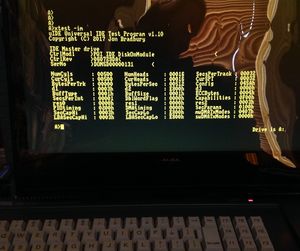
In the PCW driver distribution there is a program called XTEST.COM that tests and returns information about connected IDE devices.
There is also a version of XTEST.COM for CPC6128 CP/M Plus that you can use to check that your uIDE-16 is working correctly: File:XTEST-6128.zip
To use, issue the command XTEST, followed by any combination of the following options:
 -t[m|s]	perform IDE diagnostic on m (master) or s (slave)
 -s[m|s]	summary info on m (master) or s (slave)
 -i[m|s]	interrogate m (master) or s (slave), full report
 -q	quiet mode, only prints confirmation and error messages
 -h	prints the help message and exits without formatting
If you do not enter any options, XTEST prints the help message and exits.
- Note: For the PCW and 6128, you should always use the "master" option.
Interpreting results
Errors
If XTEST reports the drive is not found or has timed out, or you do not get a sensible looking result in the summary / full report text fields, it is likely that your uIDE is not connected properly, there was an error in assembly or configuration, or you are using an IDE device that is not compatible. If you're using a CF card with adapter, make sure that power is getting to the adapter board (see CF card section for details). The IDE device should return meaningful values in these fields. For example, the 128Mb PQi DOMs return the string "PQI IDE DiskOnModule" in the CtrlModel field (left justified, space padded per the IDE spec).
Diagnostic
The diagnostic result shows the values of the Status and Error registers in hexadecimal, following an IDE Diagnostic command (90h). The Error register is only valid if bit zero of the Status register is set. Refer to the IDE spec in the downloads section, Section 9.7 ("Execute drive diagnostic") for details.
Summary information
The summary information returns the text fields from the IDE Identify Drive command (ECh). They are the Model Number ("CtrlModl"), Serial Number ("CtrlSer") and Firmware Revision ("CtrlRev") fields from Table 10 in the IDE spec (Identify Drive, Section 9.9).
Full report
The full report contains all the fields returned by the IDE Identify Drive command (ECh). Refer to Table 10 in the IDE spec (Identify Drive, Section 9.9). The fields are identified by a word offset, but XTEST uses a specific label for each. To locate the correct description for the XTEST label, refer to this table:
 XTEST label	Word	Comment
 --------------- ------- -----------------------------------------------------
 Config		0	General configuration bit field
 NumCyls	1	Number of cylinders
 res0		2	Reserved
 NumHeads	3	Number of heads
 BytesPerTrk	4	Number of unformatted bytes per track
 BytesPerSec	5	Number of unformatted bytes per sector
 SecsPerTrack	6	Number of sectors per track
 d1		7	Vendor specific
 d2		8	Vendor specific
 d3		9	Vendor specific
 SerNo		10-19	IDE device serial number
 BuffType	20	Buffer type
 BuffSize	21	Buffer size in 512 bye increments (so, 1 = 512 bytes)
 ECCBytes	22	Number of ECC bytes available on r/w long commands
 CtrlRev	23-26	IDE device firmware revision
 CtrlModl	27-46	IDE device model designation string
 SecsPerInt	47	Bits 0-7 gives sector tx max for r/w multiple cmds
 DblWordFlag	48	0001h = can perform double word i/o, else cannot
 Capabilities	49	Bit 9: LBA Supported / Bit 8: DMA supported
 res1		50	Reserved
 PIOtiming	51	Bits 8-15: PIO data transfer cycle timing mode
 DMAtiming	52	Bits 8-15: DMA data transfer cycle timing mode
 res2		53	Reserved
 CurCyls	54	Number of current cylinders
 CurHeads	55	Number of current heads
 CurSPT		56	Number of current sectors (per track)
 SecCapLo	57	Device sector capacity low byte
 SecCapHi	58	Device sector capacity high byte
 SecParams	59	Refer to IDE Spec
 LBASecCapLo	60	Total number of sectors in LBA mode (low byte)
 LBASecCapHi	61	Total number of sectors in LBA mode (high byte)
 swDMATxModes	62	Refer to IDE spec table 10
 mwDMATxModes	63	Refer to IDE spec table 10
SecCap and LBASecCap are 32 bit integers, and are printed in the correct order as hexadecimal in the report. To get the full value, concatenate them and feed the resulting value into a calculator with hex conversion. For example, a PQI 128Mb DOM has SecCapHi of 0003 and SecCapLo of E800h, which gives the value 0003E800. This is 256,000 sectors (in base 10), not quite 128MB.
Using the formatter XFORMAT.COM
XFORMAT is the program used to prepare a master or slave IDE device for use by formatting it.
To use, issue the command XFORMAT followed by any combination of the following options:
 -m	format the IDE Master device
 -s	format the IDE Slave device
 -f	force format (does not ask for confirmation)
 -q	quiet mode, only prints confirmation and error messages
 -h	prints the help message and exits without formatting
If you do not enter any options, XFORMAT prints the help message and exits.
XFORMAT does not assume a default for -m or -s, because formatting a drive removes all the drive's data, and we don't want this happening accidentally.
When you specify -m or -s, XFORMAT will format the specified devices and for each one, ask for confirmation (unless -f is specified). At this point you must enter y to proceeed (upper or lower case), or any other character to cancel. XFORMAT will then report on each partition (logical drive) as it is being formatted, by way of an ascending counter from 00 to 15.
When you specify -s, XFORMAT will print an error if no slave drive is attached to the uIDE interface.
Formatting assumes a minimum of 128MB available on the IDE device(s) being formatted. Since each partition has 8MB of space, a 128MB IDE device will yield 16 8MB partitions (but note that certain devices, such as the PQI DOM, have just short of 128MB because they round the number of 512 byte sectors down).
Using smaller IDE devices is possible though not recommended as no tests have been carried out.
You can use XFORMAT at any time. On CP/M 2.2, if the XDRIVER is loaded, XFORMAT issues a system disk reset (BDOS call 0Dh) to ensure that all disk allocation buffers are cleared down. On CP/M 3, use the XRST.COM command to achieve the same thing.
For uIDE-16 users with HDCPM, do not use XFORMAT - follow HDCPM documentation for disk prepatation.
About XRST.COM
XRST is a small utility to reset the CP/M disk system.
It's simple program that just calls the CP/M BDOS function 13 (DRV_ALLRESET) - Reset discs. You can read about the BDOS functions, including DRV_ALLRESET, here: http://www.seasip.info/Cpm/bdos.html
It is recommended you call XRST after formatting a uIDE drive with XFORMAT on CP/M Plus, because XFORMAT writes to the disk directly so the BDOS won't know that the disk buffers are stale.
Drivers
Amstrad PCW
There is a driver for the PCW which is a FID ("Field Installable Driver") file. To install it, simply copy it to your boot disk (USER 0). Not all CP/M Plus versions support FIDs though (notably the earlier ones - see below).
The driver's capabilities are:
- No configuration needed, just copy the XDRV.FID file onto the boot disk and CP/M Plus does the rest at next boot (if it is a recent enough version).
- Auto detection of the uIDE card, unloads if not found.
- Provides up to 6 CP/M drives C: D: E: F: G: H:. This appears to be a limitation of the Amstrad CP/M Plus memory map. Depending on what expansions you have connected to the PCW, you may have fewer than this (for example, if the Amstrad CPS8256 Serial/Parallel device is fitted, you lose H:).
- A later version exists that gives the full complement of drives, see below in bold and the Downloads section above.
- Is compatible with the CP/M Plus M: drive.
- Provides additional drives under Locoscript - H: I: J: K: L:.
- Each drive is 8MB in size, and supports 512 directory entries shared between 16 user areas.
- A formatter and some IDE test utilities are provided as part of the driver suite (see above). Use the formatter to prepare a CF card or DOM prior to use. Use the test utility to verify that your uIDE is connected properly and the DOM or CFD card is compatible.
The provisional PCW driver suite can be downloaded here: File:Xdriver PCW suite 0.1.zip. This contains the driver FID file and the utilities described on this page (apart from XFMT.COM which is a short version of XFORMAT.COM).
If you are using the PCW image download or one of my DOMs, you do not need this download as the files are all on on the image / DOM. Read on... ;)
A later version of the PCW driver suite is here: http://www.cpcwiki.eu/forum/nc100-nc200-pcw-pda600/announce-pcw-xdriver-suite-v1-11-for-uide-users/. This gives access to more CP/M drives without needing a reformat, and has a new formatter as there was a bug in the old one. The thread also discusses how to fix the old format non destructively.
Amstrad CPC6128
uiDE on the CPC6128 is supported by HDCPM. Kudos to d_kef!
Intertec Superbrain QD
Please see the Downloads section for a link to the Superbrain QD installation ZIP file. The README.com has installation instructions and links to pictures showing the uIDE installed on a Superbrain.
Transferring software to the PCW
I have assumed that you already have a way to get downloaded files onto your PCW. If not, the options are:
- Use a serial adapter such as the Amstrad CPS8256 and a copy of KERMIT to transfer over serial.
- Install a 3.5" floppy drive and transfer via floppies. You will need a program such as CPCDiskXP to put PCW disk image files onto the floppy. This program can also copy a downloaded file to a disk image.
- You can use cpmtools to access files on an image of your uIDE IDE device, and win32diskimager (under Windows) or dd (under linux) to copy the entire image to/from your Z80 machine's IDE device. Read the section below about the uIDE disk image.
There may be other ways to achieve this (such as using a LocoLink cable) but it is out of scope of this WIKI page. If in doubt, ask on the forum.
BASIC program to load the PCW driver from a DOM or CF card
If you choose to buy one of my DOMs, I will load it with the xdriver FID file and the uIDE image I describe below. You can also download and copy the uIDE hard disk image onto your own IDE device as this has the driver file preloaded (see below for instructions).
To get the PCW xdriver from the image, enter the following program into BASIC and run it. It will retrieve the driver from the IDE device and write it to the currently logged-in disk. The driver file is written to the first three sectors on the IDE device, so that even if you format it, you can still use the BASIC program to restore the FID (because track 0 is reserved by the driver for future use).
 10 REM uIDE bootstrap - load FID from uIDE track 0
 20 MEMORY &HCFF0
 30 :
 40 PRINT
 50 PRINT "uIDE-8 PCW driver retrieval program"
 60 PRINT "Copyright (c) Jon Bradbury 2019"
 70 PRINT
 80 REM for XDRV release v1.11 use fidStart%=&HD000: fidEnd%=&HD4FF: fidSec%=3
 85 REM for XDRV release v1.12 use fidStart%=&HD000: fidEnd%=&HD544: fidSec%=3
 87 fidStart%=&HD000: fidEnd%=&HD544: fidSec%=3
 90 cfBase%=&HC8
 100 cfData%=cfBase%
 110 cfFeatures%=cfBase%+1
 120 cfError%=cfBase%+1
 130 cfSecCount%=cfBase%+2
 140 cfLBA0%=cfBase%+3
 150 cfLBA1%=cfBase%+4
 160 cfLBA2%=cfBase%+5
 170 cfHead%=cfBase%+6
 180 cfStatus%=cfBase%+7
 190 cfCommand%=cfBase%+7
 200 cf8Bit%=1
 210 cfReadSec%=&H20
 220 cfMaster%=&HE0
 230 cfSetFeat%=&HEF
 240 tout%=0: addr%=fidStart%
 250 GOSUB 850
 260 :
 270 GOSUB 580: REM cfWait
 280 IF tout%=1 THEN GOTO 560: REM check for timeout
 290 :
 300 REM init IDE device
 310 CALL di%
 320 OUT cfFeatures%,cf8Bit%
 330 OUT cfCommand%, cfSetFeat%
 340 CALL ei%
 350 GOSUB 580: REM cfWait
 360 :
 370 REM retrieve FID
 380 PRINT "Retrieving driver: [                        ]";
 390 FOR x=0 TO 24: PRINT CHR$(8);: NEXT x
 400 FOR secNo% = 1 TO fidSec%
 410 GOSUB 680: REM get current sector
 420 NEXT secNo%
 430 PRINT
 440 PRINT "Writing xdrv.fid:  [                      ]";
 450 FOR x=0 TO 22: PRINT CHR$(8);: NEXT x
 460 OPEN "R",#1,"xdrv.fid",1
 470 FIELD #1,1 AS d0$
 480 FOR addr%=fidStart% TO fidEnd%
 490 LSET d0$=CHR$(PEEK(addr%))
 500 PUT #1
 510 IF addr% MOD &H40 = 0 THEN PRINT CHR$(128);
 520 NEXT addr%
 530 CLOSE #1
 540 PRINT: PRINT: PRINT "Done."
 550 PRINT "Copy xdrv.fid to your PCW CP/M boot disk and reboot."
 560 END
 570 :
 580 REM cfWait
 590 FOR try%= 0 TO 31
 600 CALL di%
 610 status% = INP(cfStatus%)
 620 CALL ei%
 630 IF (status% <> &HFF) AND (status% AND &H80 <> 0) THEN RETURN
 640 NEXT try%
 650 PRINT "IDE device timeout - check it is connected."
 660 tout%=1
 670 RETURN
 680 :
 690 REM get sector in secNo%, copy to buffer
 700 CALL di%
 710 OUT cfLBA0%,secNo%
 720 OUT cfLBA1%,0
 730 OUT cfLBA2%,0
 740 OUT cfHead%,cfMaster%
 750 OUT cfSecCount%,1
 760 OUT cfCommand%,cfReadSec%
 770 CALL ei%
 780 GOSUB 570
 790 FOR byte%=0 TO 511
 800 POKE addr%,INP(cfData%)
 810 addr%=addr%+1
 820 IF addr% MOD &H40 = 0 THEN PRINT CHR$(128);
 830 NEXT byte%
 840 RETURN
 850 :
 860 REM load up ei-di routines
 870 DATA &HF3,&HC9,&HFB,&HC9
 880 FOR x=&HCFF1 TO &HCFF4
 890 READ inst%
 900 POKE x,inst%
 910 NEXT x
 920 di%=&HCFF1
 930 ei%=&HCFF3
 940 RETURN
To use the program.
- Turn the PCW off.
- Connect the uIDE to the PCW.
- Plug the DOM or CF card into the uIDE's IDE socket. If using your own, copy the PCW uIDE image onto it first.
- Power up the PCW. If the uIDE power and activity lights both come on, you have the cable or DOM back to front. Power down and check, then power-on again.
- Load Mallard BASIC and enter the program. It's easier if you type AUTO 10 first. Take care with the entering of variable names, most of them have a % at the end (integer).
- Save the BASIC program down before running it. SAVE "get-xdrv.bas"
- Return to CP/M by typing SYSTEM
- Copy get-xdrv.bas onto your boot disk and run it from there. From CP/M: BASIC get-xdrv
- You should see a progress bar as the FID is loaded from the DOM. The activity light on the uIDE should be flashing.
- Now a second progress bar comes up as the FID is being written to the floppy drive.
- When the program ends, return to CP/M with the SYSTEM command.
- Reboot the PCW (use LEFT-SHIFT - EXTRA - EXIT key combination rather than the power switch, it's quicker).
- You should see the sign-on message "PCW IDE Extended Driver Copyright (C) Jon Bradbury"
- You should also see a list of available drives.
- Try entering DIR C:. if it shows a list of files, your uIDE is working! Otherwise, there's something wrong and you will need to check your assembly. If I assembled it, contact me immediately.
- It is wise to make a backup of the xdrv.fid file and the BASIC retrieval program onto a separate floppy disk.
uIDE disk image and utils download
There is a zip file containing a disk image of CP/M software that you can download here: File:UIDE-PCW.zip
It also has cpmtools and win32diskimager software.
The Zip file contains the following:
| File / folder | Description |
|---|---|
| BASIC-FILES | Directory containing a collection of BASIC programs and Microsoft interpreter / compiler |
| cpmtools | The CPM tools package, with additional disk defines for accessing a uIDE disk image. |
| Win32DiskImager-0.9.5 | The disk imaging program for Windows, works under Windows 10 x64 as well. |
| WS4-FILES | Directory containing a copy of Wordstar 4 |
| Making CPM Images.pdf | A very well written guide to creating CP/M images on IDE devices, written by the guys at www.s100computers.com. |
| uide.img | The PCW uIDE disk image (see below). |
The Intertec Superbrain uIDE disk image is called sbuIDE v0.11.img and is distributed as part of the Superbrain download package (see "Downloads" sectiopn above).
The PCW disk image is called uIDE.img and it is a copy of the N8VEM image, with the PCW uIDE driver loaded, as well as some PCW specific files (on drive C:, User 0) and additional games.
Image contents
The image contains the following (where the number is the USER number - see below).
 --------------------------------------------------------------------------
  C:              D:              E:                F:
 --------------------------------------------------------------------------
  0 PCW SPECIFIC  0 GAMES         0 OLD UTILS       0 NEWUTILS
  1 BDS_TINY_C    1 MUMATHSIMP    1 F80,M80,BASIC   1 FREE
  2 APL           2 CROSSTALK     2 AZTEC_C_106D    2 Z SYSTEM
  3 JANUS_ADA 1.5 3 QTERM43       3 TURBO PASCAL 3  3 MICROPRO
  4 MS_COBOL      4 CLINK         4 DX-FORTH 4.01   4 MULTIPLAN
  5 PILOT         5 SUPERSOFT UTL 5 PL/I 1.4        5 DBASE II
  6 SYSLIB        6 RCP/M         6 ALGOL/M         6 FREE
  7 BBC BASIC     7 DDTZ SOURCES  7 SUPERCALC       7 FREE
  8 NEMESIS       8 ADVENTURE-80  8 ASM GAMES       8 MICROSHEL
  9 GAMES         9 ZCHESS        9 MORE GAMES      9 INFOCOM ADVENTURES
                 10 ZORK         10 NEMESIS        10 BASIC GAMES 1
                                 11 YET MORE GAMES 11 BASIC GAMES 2
Note: The original N8VEM downloads are here (including manuals for many of the included programs): http://obsolescence.wixsite.com/obsolescence/n8vemimage
Some tips for using the CP/M programs on the disk image
- Download the manuals from the N8VEM website!
- Be aware that these programs and applications were written for CP/M 2.2 and some of them might not work on CP/M Plus.
- Many of the games are a bit poo. Remember, it's all text based, but if you fancy hunting a Wumpus or playing Trek, or even trying a classic Infocom adventure, you've come to the right place.
- In C0 there are versions of some programs that are specific for your machine. Always use these in preference to any version found elsewhere on the image. For example, ZSID.COM and KERMIT.COM on the PCW image are PCW specific.
- Where a program or application needs you to tell it what type of terminal you are using, choose "Zenith" or "Heath". If that doesn't work, try "VT52". These are closest to what the PCW emulates.
- WordStar and other Micropro applications are located in F3.
- Use an Internet search to find out about the programs you do not recognise.
- Most of the BASIC programs are written for Microsoft BASIC-80, which is located in E1. Remember to use SYSTEM in MBASIC to return to CP/M.
- You might find multiple copies of some of the programs on the image.
- Any user areas you don't want or need can be deleted.
- Drive G: and H: are empty.
If your DIR just shows : characters (G: and H:)
There is a possibility of G: and H: not having properly setup directory entries on the image. When you do a DIR, you might see something like this:
 G:>DIR
 :        :        :        :
 :        :        :        :
 :        :        :        :
 :        :        :        :
 :        :        :        :
 :        :        :        :
 :        :        :        :
 G:>
If this happens, do the following:
G:>ERA *.*
..and answer y to the "delete all" question. This will sort out the directory.
Copying the disk image to an IDE device
I use a special cable setup to connect a DOM to my PC via USB for image transfers.
The various parts are labelled:
- IDE-USB adapter. Get this from any online auction site.
- Power connection (if your IDE-USB adapter doesn't supply power to IDE pin 20). Pin 20 is the red wire, +5v. Pin 19 is GND. I use a 2 pin PCB header to connect to the female IDC connector.
- IDE device, in this case a 128Mb DOM
- 5v power supply. This is only used to power the IDE device, and if you are using a CF card adapter, you may find it has a power socket you can use instead.
- Cable. This is a simple 40 way IDC ribbon cable with two cable mounted male IDC box headers and two cable mounted female IDC plugs (you only need one, for connecting power to the IDE device). The parts to make this up are freely available, and the cable can be used to connect a slave drive to uIDE.
There are other ways to connect your IDE device to a PC:
- If your PC has a spare IDE connector, you can plug the DOM or CF card adapter device directly into it.
- If you are using a CF card, you can connect it to your PC with a standard USB-CF card adapter.
To transfer the uIDE image under Linux
Use the Linux dd command to do this, but take care that the of= parameter is pointing to your IDE card. Use GParted to verify this.
The command is:
sudo dd if=uide-image-file of=the-device-of-your-IDE-card
Example:
sudo dd if=uIDE_download.img of=/dev/sdc
If in doubt, read the dd manual by entering the command
man dd
..and be aware that dd is also known as the "disk destroyer" because if you get the -of wrong your hard disk may be wiped. I use GParted (under Ubuntu Linux) to ensure I have the correct device by loading it up and looking in the dropdown for the list of disks. One of them will be 125MB and that is the DOM. You'll see it is named as "/dev/[something]" - that's what your dd -of argument should be.
To transfer the uIDE disk image under Windows
Later Windows versions are not very good at giving low level access to hard drives like Linux is. Transferring images is, therefore, a bit more convoluted (and so far I have not found a way of reading images back, because Windows will not recognise the hardware unless the drive on it is formatted for DOS or Windows).
This procedure should get you started, though.
- Connect the transfer rig to your PC
- Insert the IDE device and power it up.
- If Windows Explorer does not show the drive it is unformatted or uninitialised. Initialise it first via "Computer Management" (On the Start menu, under All Programs -> Windows Administrative Tools, or Run -> compmgmt.msc). Click the Storage / Disk Management item in the left hand side of the screen and you should see the IDE device in the main pane. Right-click on the button labelled "Disk n Unknown" (n depends on how many drives you have) and select "Initialise Disk". Select MBR and click OK. Now click on the "Unallocated" block for the disk and select "New Simple Volume", then (in the New Simple Volume Wizard, click Next, Next, Next, Next, Finish). If you get a popup saying the disk needs to be formatted, cancel it, because the Disk manager is already doing it. Now, go back to Windows Explorer and you should see a disk called "New Volume". Note the drive letter.
- Launch Win32DiskImager. Select the drive letter of your CF card or DOM on the right of the window and choose the uIDE disk image file on the left, then click the "Write" button. Check that the confirmation dialog box shows the correct drive letter, then click "OK". You should now see a progress bar as the image is written to the IDE device. When complete, a small widow will pop up saying "Write successful." Click the OK button and close win32imager.
- You should now have a prepared uIDE DOM or CF card. Disconnect the imaging cable and power down the IDE device. Plug it into the uIDE adapter.
- In case of problems, try using a powered USB hub to connect the USB-IDE adapter to your computer. Some of the cheaper ones (like mine) seem to try and draw more power from the USB port than is allowed, and can be unreliable as a result.
To retrieve the uIDE driver from the IDE device
Before you can use uIDE under CP/M, you must retrieve the driver file that is stored on the uide image.
- Follow the instructions above (the BASIC program) to retrieve the xdriver FID file from the IDE device. After rebooting your computer, you should able to explore the disk image.
To access files on the uIDE image
Use the cpmtools executables that are in the downloaded zip file. Copy the uide.img file to the cpmtools directory and try the following:
C:/Users/JonB/uIDE/cpmtools>cpmls -f uIDE0 -d uide.img
Lists all files on drive 0 (first CP/M partition on the image). To see the other partitions, substitute uIDE0 with uIDE1, uIDE2, uIDE3 and so on. A uIDE disk image has 16 partitions (although remember, under Amstrad CP/M, only the first six are accessible).
C:/Users/JonB/uIDE/cpmtools>cpmcp -f uIDE0 uide.img 0:pcwexpan.txt pcwexpan.txt
Copies the file pcwexpan.txt on drive zero, user zero in the uide.img file to the current directory.
C:/Users/JonB/uIDE/cpmtools>cpmcp -f uIDE2 uide.img more.com 3:more.com
Copies the CP/M program MORE.COM from the current directory to drive 2, user 3 of the uide.img image file.
If you are transferring files to an image, remember you have to then put the image back onto the IDE device before you can access it on your Z80 computer.
Refer to http://www.cpm8680.com/cpmtools/ for more information.
Short disclaimer
The uIDE disk image is supplied "as-is" and the copyrights of the respective authors are acknowledged. Please do not PM me if you encounter problems with any of the applications - ask on the CPCWiki PCW forum (or better still, the VCF CP/M forum). There is no guarantee that all applications will work on your machine; they are CP/M 2.2 programs provided with the intention of helping to get you started with your uIDE device.
CP/M Plus version requirements
To use the PCW uIDE xdriver, you must have a version of CP/M Plus that supports FID ("field installable driver") files.
- On the PCW8256 and 8512 the lowest FID supporting version is 1.14. That's "one dot fourteen" so if (like me) you have v1.4, yours is too old.
- On the PCW9512 you should be OK. I have v2.15.
Refer to http://www.seasip.info/cpm/amsfid.html for more details.
If you find your CP/M Plus version is too old, it should be sufficient to replace the EMS file on your boot disk with a later one. The file containing CP/M is named like "JnnCPM3.EMS" or "JnnCPM3.EMT". The nn indicates the version number so for example "J14CPM3.EMS" is version 1.4. If your boot disk's CPM file has a ".EMS" extension and you want to use a file with ".EMT", just rename it (and vice versa).
PCW8000 series CP/M versions
You can download a ZIP file with the later PCW EMS/EMT files here: http://www.cpcwiki.eu/forum/nc100-nc200-pcw-pda600/cpm-plus-1-11-1-5-download/?action=dlattach;attach=21886
(From this thread http://www.cpcwiki.eu/forum/nc100-nc200-pcw-pda600/cpm-plus-1-11-1-5-download/ )
For the 8256 / 8512 machines, I recommend the v1.15 EMT file.
Future extensions
There are no plans as yet to produce any of these extensions because I'm busy building uIDE devices and I need some commitment from buyers before sinking the huge amounts of time and money required to do them. So, if you are interested, please let me know.
Z80 Bus board / backplane
Building on the Z80 bus concept employed by uIDE, I have completed the design of a 5 slot bus board.
It needs a quick rethink though, because I would like to add some additional lines for special host pins such as are found on the PcW.
PCW Serial / parallel port
The easiest way to routinely transfer files between a CP/M machine and a PC is via a serial connection and transfer software such as Kermit. The problem is that on the PCW and 6128 you need a plug-in adapter (and these are a bit hard to come by).
The PCW adapter is called a CPS8256 and it has both serial and parallel ports. It is not compatible with the PCW 9512.
This is a design for a parallel / serial adapter to plug into the Z80 bus board that is a clone of the CPS8256.
uRTC-8 Real Time Clock
This board is an external RTC that enables the host computer to maintain the time and date even when switched off.
Please see URTC-8 Universal RTC for Z80 computers for more details.
PCW uIDE boot card
This board would enable the PCW to boot directly from the uIDE board. A bit complicated but I intend to have a go at it... It's special in that it requires access to the "unused" pins of the PcW expansion port adapter - these are /REFSH, /NMI, /HALT, /MDIS, 3.2Mhz respectively (the boot card really needs /MDIS as far as I know). Others have implemented hard drive booting on the PCW, and I need to find out how - then I can build this card.
Other expansions
I have been thinking of other expansions. Some possibilities include:
- Parallel GPIO card
- Dk'tronics sound clone
- AMX mouse clone
Connecting a CF card to uIDE instead of a DOM
Not recommended due to compatibility problems with some types of CF card, but if you really must, you need a cheapo IDE to CF card adapter and you should either connect its 5v input to the uIDE CF_PWR header (being VERY careful about the polarity) or modify the adapter so that IDE Pin 20 is connected to the 5v power socket, as shown on the left. The thin copper wire that goes from the IDE plug to the small component next to the power socket is the mod. You should check with a meter that these are correct for your adapter. Some adapters already have this connection, so try yours before modding it. You should see its power light come on if it is properly connected.
CF Card compatibility list
My intention is to maintain a list here of which CF cards work with uIDE, and which do not. So:
| Card make / type | Comments |
|---|---|
| Verbatim 64MB CF card | works |
| Dane-Elec 512MB CF card (C1 512 D-SA) | works (this card identifies as a Samsung) |
| Kingston CF 16GB 266X | not compatible, will not identify |
| STEC 128MB CF SLCF128MM1U | not compatible, will not identify |
About CP/M USER areas
This section was written for xdriver v1.9 under CP/M 2.2 and may or may not apply to CP/M Plus.
A CP/M "user area" is a bit like a directory under MS-DOS, except it is named by a number and there are only 16 of them on each drive.
To use the different user areas, use the command USER n where n is the user area you want to switch to (0 to 15). It is tricky copying files between user areas. First you need to get PIP.COM to the user area you want to copy to.
The DRI PIP manual says:
 To copy files into another user area, PIP.COM must be located in that user
 area. Use the following procedure to make a copy of PIP.COM in another
 user area (in this example, USER 3).

 USER 0			Log in user 0.
 DDT PIP.COM		(note PIP size s) Load PIP to memory.
 G0			Return to CCP.
 USER 3			Log in user 3.
 SAVE s PIP.COM

 In this procedure, s is the integral number of memory pages, 256- byte
 segments, occupied by PIP. The number s can be determined when PIP.COM
 is loaded under DDT, by referring to the value under the NEXT display.

 If, for example, the next available address is 1D00, then PIP.COM requires
 1C hexadecimal pages, or 1 times 16 + 12 = 28 pages, and the value of s is
 28 in the subsequent save.

 Once PIP is copied in this manner, it can be
 copied to another disk belonging to the same user number through normal
 PIP transfers.
You can now change user or drive as many times as you like, and drop a copy of PIP.COM using the same save command, as long as you do not run any transient commands in the meanwhile (this means, "execute a .COM file").
Copying files between user areas.
To copy files to a particular user area, first switch to it with 'USER n' command. Then, use the PIP you SAVEd to the user area to copy files in:
PIP dr:<filespec>[Gn]
where
- dr: is the source drive ID (A: - P: ), and
- n is the source USER area.
Example: To copy KERMIT.COM from Drive A USER 5 to Drive N User 15 (assumes PIP.COM is already present in the target drive / user area):
 A:>N:
 N:>user 15
 N:>pip n:=a:kermit.com[g5]
More fun with CP/M Plus
Some of this stuff you probably know.. but anyway, in case you don't...
Faster loading of CP/M COM files on the PCW
One of the first things you should do after setting your uIDE up is to copy all the CP/M program files to one of the IDE drives so that they load quicker.
To do this (and assuming you want to put these all on the C: drive):-
- Insert CP/M boot disk into the floppy drive A:
- Issue the command PIP C:=A:*.*[v]
- The [v] option will verify each file after it is copied. Since this is likely to be the first thing you do with the uIDE, it's a good idea to use [v] just to double check it's working OK.
- Now create a file called PROFILE.SUB on the boot disk in A:
- Add the line C:SETDEF M:,C:,* [ORDER = (SUB,COM)] and save the file
- What this does is make the CCP (command line processor) look for SUB and COM files on the IDE drive C: before the currently logged disk. So if you are on A: and you issue the command BASIC (to load BASIC), it will be loaded from the IDE drive rapidly, even if there is a copy on A:. In fact, it looks on M: first, and a submit file like BASIC.SUB takes precedence over the real executable BASIC.COM.
Public USER 0 (SYSTEM files) on the PCW
Another useful trick is to make the CP/M COM files in user area 0 into SYSTEM files. This means that they won't be visible when you do a DIR, and they will be executable from all user areas on the same disk. So:-
- Go to the drive where you copied all the COM files to. In this example, it is C:
- Switch to USER 0 (type "USER 0" at the CP/M prompt).
- Enter the command SET *.* [SYS]
- Now, when you switch to another user on the same drive, you can access the CP/M command set without copying them to the user area first.
- If you do this, there's no need to copy PIP to all the user areas (this was required for CP/M 2.2).
- If you want to turn them back into normal files, enter the command SET *.*[DIR]
- If you want to list them, enter the command DIR[SYS] (note, needs the program DIR.COM installed)
Fast switch between any drive / user combination on the PCW
One last info nugget, which you should find useful when looking through the download image. You can go to any drive / user combination by typing DN: where D is the drive letter and N is the user number. CP/M alters the CCP prompt to tell you where you are. For example:
 A>C10:
 10C>
Curiously, it puts the user number first. If you just enter the drive letter, it switches to the drive you specify, but leaves the user number unchanged:
 10C>D:
 10D>
When you are in USER 0, it does not show a user number in the CCP prompt.
More information
PCW uIDE prototype demonstration videos
Superbrain uIDE discussion thread on VCF Forum
Superbrain QD uIDE demonstration videos
File:IDE SPEC.PDF - IDE Specification document
Copyright
All designs presented here are copyrighted works.
Copyright (C) Jon Bradbury 2017.
- VCF Forum http://www.vcfed.org/forum/forum.php member "JonB"
- CPCWiki Forum http://www.cpcwiki.eu/forum/forum/ member "JonB"
- Amstrad.ES Forum member "JonB"
Disclaimer
As I am a hobbyist, not a big business, I need to make a few things clear.
You are free use these designs for personal purposes only, on the following conditions:
- You do not attempt to take credit for the work I have put into designing and / or building any device offered here.
- You acknowledge my right to assert copyright and ownership of these designs.
- You agree to indemnify me and the CPCWiki web site against damage to your computer or other connected hardware or data contained on any attached media.
- All work is undertaken at your own risk. I am not liable for any hardware damage or data loss, loss of your homework, your dog getting sick, etc.
- All devices and/or PCBs I offer are supplied as-is and there is no warranty that they are fit for any particular purpose.
- Use for any commercial purpose is explicitly forbidden, this includes reverse engineering, selling or reselling the design or boards.
- Your agreement to these conditions is implicit on ordering any of these devices or PCBs from me.
Support
I will support your use of these designs via the appropriate forum by offering help and advice as necessary. Please review the content of this Wiki page before asking for help, though, and contact me via the channels described below.
How to contact me
I am member "JonB" of the VCF and CPC Wiki Forums. If you need support or have any comments, please start a new thread on the VCF CP/M forum here:
http://www.vcfed.org/forum/showthread.php?56162
Or on the relevant CPCWiki / Amstrad.ES forum linked to above. You could also PM me.. :)
Note: Forum registration is required.
Acknowledgements
I would like to thank some collaborators for their work and kind assistance.
- Grant Searle, who wrote the original formatting program and read / write driver code as well as the DPB for his nine chip CP/M computer. XDRIVER is a derivative of this work. http://searle.hostei.com/grant/index.html
- John Elliot, who helped me to understand how the FID file format works, and provided his FID CHECKSUM program which is a required part of the FID development toolchain. http://www.seasip.info
- CPCWiki member Bryce, who provided a good deal of hardware advice and encouragement. Bryce is also a uIDE beta tester.
- The open source community team responsible for KiCad, which, in its later incarnations, is worth every penny you do not have to spend on it. http://kicad-pcb.org/
- CPCWiki member d_kef, who has written HDCPM which allows uIDE-16 to work under CPM Plus on the CPC6128.
Salutation
Cheers!
CPCWiki Forum Member "JonB" (Jon Bradbury) 19/02/2017
