Disclaimer: Adding ram to the GX-4000 is mostly useless. The only reason I did this is for fun...
1) Get two CPC-Plus compatible ram, and a 10 kΩ resistor
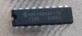
I used KM41464AP-12, but there are other chips of the same kind that should work.
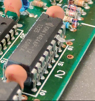
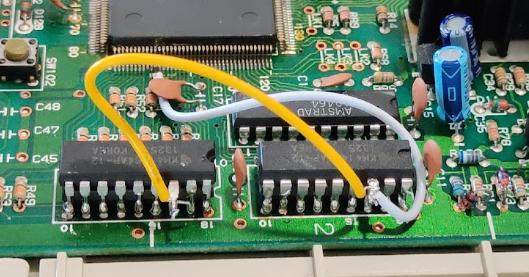
2) Solder them both piggy back on the existing ram chips, except for the NCAS signal (pin 16)
Leg 16 is used by the ASIC to select the RAM bank to use. All other signals are totally parallel.
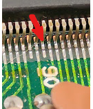
3) Pin 16 of both ram chips must be connected to ASIC NCAS1 (pin 91)
It is very easy to spot this leg, since it is the one just after the 90 written on the board, and it is not connected to anything.
(Beware, pin 89 just on the other side is a ground pin. Using it would select the RAM for all access and mess up everything.)
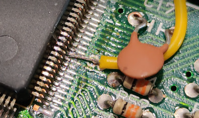
This is the tricky part: soldering the wire to this leg is rather difficult, since it is very small. Also double check that no connection occurs between the surrounding legs afterwards. (Using an ohmmeter, for example.) I used the ceramic capacitor to hold the wire in place while soldering.
Here is what it looks after soldering wires on RAM legs 16.
(I'm not that proud of my color choices, nor of my soldering skills...
4) Telling the ASIC it should use this RAM.
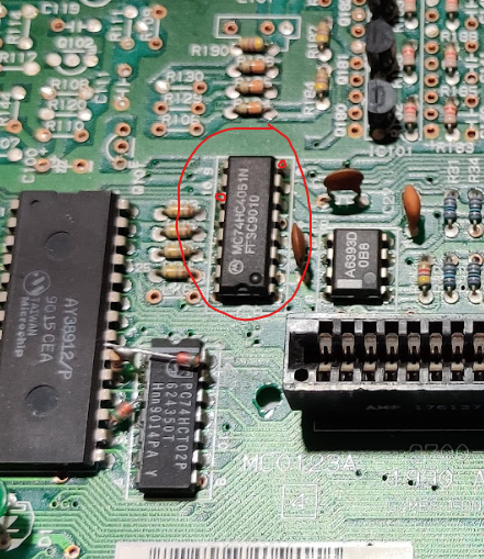
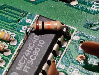
For now, these chips are totally ignored by the GX-4000. It needs to be told that CAS1 must be used. To do so, the 10 kΩ resistor must be added to match the resistor present in the 6128 plus. The easiest place to solder it is on this 74HC4051 chip, pulling down its pin 11 using pin 8, which is ground.
It's worth noticing that this resistor is labelled R128 on the 6128 schematics, thus enabling 128k of ram.
Here is the resistor installed...
