Introduction
As most readers will know, the 464+ uses exactly the same PCB as the 6128+, just that the 6128+ specific components for the extra 64K and floppy control have not been installed. The following guide will explain what parts you need and how to go about converting your 464+ to a 6128+.
What You Will Need
Other than the obvious tools required such as a soldering iron, cutters and a screw driver, there are quite a few components you'll need to source. Some of these are standard components that are still readily available and cheap to acquire, others such as the SED9420 Data Separator, the µPD765 Floppy Controller and the RAM ICs may prove more difficult to find.
Here's a list of all required parts:
| Part No. | Value | Note |
| IC3 | SED9420 | Data Seperator |
| IC4 | µPD765 | Floppy Controller |
| IC5 | 74LS38 | Quad 2 Input NAND Gates |
| IC6 | 74LS38 | Quad 2 Input NAND Gates |
| IC7 | 74HC14 | Hex Inverting Schmitt Trigger |
| IC12 | 41464 | 64K x 4bit Dynamic RAM |
| IC13 | 41464 | 64K x 4bit Dynamic RAM |
| R6 | 820K 1/8W | |
| R7 | 2.2K 1/8W | |
| R8 | 1.5K 1/8W | |
| R9 | 33K 1/8W | |
| R10 | 82K 1/8W | |
| R11 | 6.8K 1/8W | |
| R12 | 2.2K 1/8W | |
| R28 | 10K 1/8W | |
| R29 | 10K 1/8W | This may already be fitted on some 464+ boards. |
| R55 | 33R 1/8W | |
| NR01 | 6x680R SIL Star Network | |
| C3 | 10nF 50V Polyester | |
| C4 | 100nF Ceramic | |
| C12 | 100nF Ceramic | |
| C13 | 100nF Ceramic | |
| C20 | 10nF 50V Polyester | |
| C21 | 47nF 10V Polyester | |
| C22 | 1nF 50V Polyester | |
| C23 | 10nF 50V Polyester | |
| C39 | 470µF 10V Electrolytic | |
| L04 | 125µH 2A Filter | Filter to block spikes coming from the floppy motors |
| CD04 | 2x13 2,54 Pitch header | |
| JD04 | 36way PCB mounted Centronics Socket | |
| 1x 40pin IC Socket | ||
| 1x 24pin IC Socket | ||
| 2x 18pin IC Socket | ||
| 3x 14pin IC Socket | ||
| Floppy Power Connector / leads | "Borrow" this from an old PC PSU or Adapter |
Finding The Right Parts
A few further notes about components: All resistors are rated at 1/8W which are not that easy to find these days. 1/4W resistors are fine, but they are slightly longer than the footprint holes on the PCB, so you will need to solder these in the standing position. R8 is wrongly listed as 1.5Ohm in the Service Manual Parts List, in reality it's a 1.5K resistor.
The part numbers above correspond to the labels on the PCB, the Service Manual adds 100 to all part numbers (ie: R8 on PCB is R108 in the Parts List).
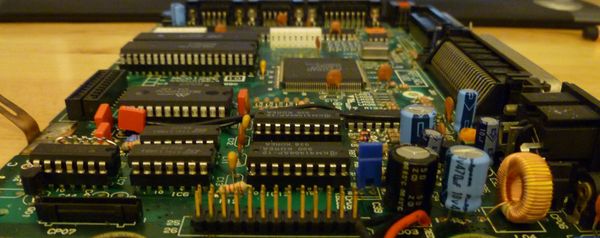
The Polyester type capacitors used in the 6128+ are also very difficult to find as they haven't been produced in that form for many years. Polyester based MKS capacitors should be used for these (The red box type which can be seen in the picture below), ceramic or standard multi-layer capacitors are not advised. They may work, but this is far from guaranteed. As MKS capacitors are very rigid, make sure that the pin distances are correct for the PCB footprint. For the ceramic capacitors, any standard multilayer non-poled capacitor will do.
The 74HC14 must be a HC type, LS or other types will not work.
There are several compatible equivalents for both the µPD765 and the 41464 DRAM ICs, which may be easier to source than these originals.
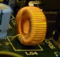
LR04 is used to filter supply spikes from the floppy motors getting back to the main PCB. The original part SN8D-500 is a 125µH filter rated at 2A.
If you can find the original part then use it, if not any filter between 100µH and 150µH with a rating of 500mA or more should work fine, especially if you intend connecting a modern 3.5in floppy which uses less current than an original 3in Amstrad floppy.
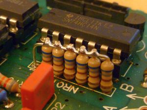
NR01 is a network of 680Ohm resistors in star configuration, this part can be hard to find, but it can be also created with six standard resistors as I have done...
If you are using a proper resistor network component, a white dot on the component marks pin 1 which should be located in the pin nearest the back of the CPC.
Preparing The PCB
After removing the PCB you'll notice that all the holes for the new parts have already been filled with solder. Amstrad didn't do this to make
it harder for you to convert, this is merely a side effect of the wave soldering process that was used to solder the board. So the first thing
you'll need to do is remove all this solder. You can do this using de-soldering gauss or a pump, depending on your preference. Don't use a drill! Drilling will damage the via connections inside these holes! In most cases you can apply a decent amount of heat to remove the solder, however be careful when preparing the holes for the 41464 RAM IC's as they are very close to the original 64K ICs and too much heat in this area could damage the original RAM ICs. C4 and R55 are also directly connected to the ASIC, so care should be taken when soldering these parts too.
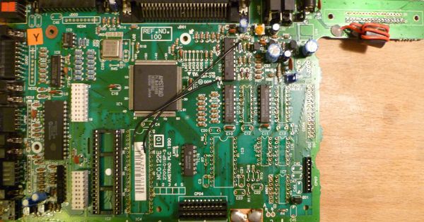
You will also notice that there are two black bridge wires running from the top of the PCB down to two of the holes you need to use for C21 and C23. These connections will still be required after the mod, so you will need to remove and later re-connect the bottom end of these wires to the legs of the capacitors. Take note of which wire goes to which capacitor!
Although most of the parts are concentrated around the bottom right area of the PCB, there are a few other parts hidden around the board that need to be added. R28 (Directly behind the analogue joystick port) tells the ASIC that the CPC has 128K instead of 64K. R55 (between the ASIC and first RAM IC) connects the NCAS1 signal to the new RAM. LR04 and C39 (above the 26way floppy header) are required to supply the floppy disk with power. C39 is the only passive component with poles. Make sure that it is soldered in the correct position, with the minus pole towards the rear of the CPC.
Adding The New Parts
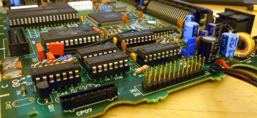
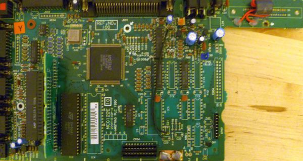
When all the holes have been cleared the board should look something like this:
Althought the new ICs could be soldered directly to the PCB, I chose to use sockets to make any future modifcations or repairs easier. There is more than enough room inside the case to allow for the extra height needed for the sockets. The components can be added in any particular order, although to make testing and debugging easier, I added only the 64K RAM components first and tested this before I continued with the floppy control components. The minimum parts required to get the extra 64K working are: R28, R55, C12, C13, IC12 and IC13. Remember that the black bridge wires must also be connected in order for the CPC to run in this state.
If you intend adding an ABBA switch to the CPC, it's a good idea to make the modifications to the external floppy connector before you solder it to the PCB. If you have borrowed the floppy power connector and leads from a PC, then you will need to remove the yellow wire from the connector and move the red wire to the position where the yellow wire was, as Amstrad (in their infinite wisdom) decided once again to steer clear of unnecessary things such as standards.
When all the components have been added the board will look quite a bit fuller and you should now have a 6128+ PCB in front of you.
Case Modifications
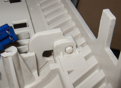
If you have chosen to add the external floppy connector, you will need to cut the additional hole in the casing, but no other external case modifications are required. However, the left hinge of the tapedeck lid will hit the back of the external floppy connector and the lid won't close properly. A small part of the hinge needs to be filed down to get the lid to close properly.
Tape Functionality
The tape functionality will still be there, but will require the |Tape command from now on.
Bryce.
Jonathanen's Easy Way To 464+ Conversion
- All you need to do is to follow the steps from 2 - 4 on "Expanding 464 to 6128 Specification - For CPC 464 Series only!!" instructions, as its very similar to CPC 464 modifications or simply, just take out the following peripherals as mentioned in Step 3 on "Expanding 464 to 6128 Specification" from your CPC 464 and transfer them to CPC 464+, except you need an adaptor - "Widget: Plus (Centronics) to Card Edge Converter" (UK/DE Expansion Converter) first - see Connecting a Disc Interface to CPC464+ and must sure it is plugged into "Expansion" socket.
- After all that, you can then play games or load programs on Tape, Cartridge or either 3” or 3.5” Discs. The choice is yours! See! Its very simple - no soldering required.
Notes:
- Its very easy and I was right all the long. Also, I both find it out and experiment it all by myself, easy and very simple way to upgrade Amstrad CPC 464+ to CPC 6128+ spec without the need to get your hands dirty - no soldering required!
- Even its works perfectly on the Amstrad 464+ with a Rombo 8 Socket ROM Box, but you'll need "Widget - Plus to edge connector" (UK/DE Expansion Converter) after I tested everything out completely, like (my very favourite testing stage for 3.5” disc drive) booting up CP/M Plus disc in drive A with no disc in drive B to make sure that 3.5” disc drive has a "READY" signal by seeing “2 disc drives” on the screen when starting up CP/M Plus. Transferring DSK files back and fourth to PC and back to CPC, using MS800, ParaDOS (replaced with the existing AMSDOS / CPM bootstrap ROM inside the disc interface) & CP/M Plus to format, copy discs onto 3.5” disc as well.
- I was both very proud and over excited as it works like a dream, as I exactly always wanted for a long, long time. Speaking of which, I prefer to use upgraded 464+ more than unexpanded 6128+ as unlike the CPC 664 / 6128, the CPC6128+ does not have a cassette connector (the CPC6128+ is missing the hardware required for cassette support), and therefore it is not possible to use cassette software without modification to the computer.
