This is a simple project to add a reset button to your Amstrad. The reset button is ideal because it will help to prolong the life of the power switch. When pressed and then released the computer will be reset and the result is the same as switching it off and then on.
The reset button can be fitted internally (requiring minimal modification to the computer) or externally.
For both options you will need:
- wire
- a push button
WARNING: You are dealing with 0.005 kilovolts. You do this project at your own risk!
Connections of the Reset Button
NOTE: The button can be connected to /RESET output (pin 41) or /BUS RESET input (pin 40) on expansion port. Of which, BUS RESET is the correct pin (RESET would work too, but it wouldn't reset the PIO, and it would cause a harmless shortcut on a logic gate).
Internal Reset Switch
- Dissassemble the computer
- Locate the BUS RESET track at the expansion port (pin 40) The position of pin 1 is marked on the P.C.B.
- Solder one end of a piece of wire to the track, and the other end to one of the pins on the push button.
- Locate the GND track at the expansion port (pin 2). There are other GND connections on the circuit board that can also be used.
- Solder one end of a piece of wire to the track, and the other end to the other pin on the push button.
- Drill a hole into the top part of the case and push the button through.
- Fix the button to the case using the nut provided.
- Re-assemble the computer
- Test!
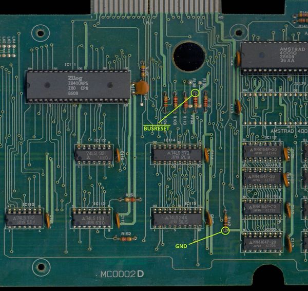
Alternative points on the 464 Mainboard to connect an internal reset button
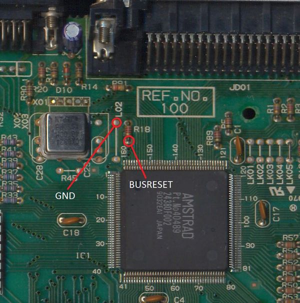
Safe points for a reset switch on a CPC464/6128 Plus
External Reset Switch
For the external reset button you will need a plug for the expansion connector. (a 50-way female edge connector for an English CPC).
- Locate the BUS RESET pin at the plug (pin 40)
- Solder one end of a piece of wire to the pin, and the other end to one of the pins on the push button.
- Locate the GND pin at the plug (pin 2).
- Solder one end of a piece of wire to the pin, and the other end to the other pin on the push button.
- Switch the computer off
- Connect the plug to the expansion connector
- Switch the computer on
- Test!


