Technical
- Uses a 16KB ROM paged into memory at &0000.
- Uses a 8KB static RAM paged into memory at &c000-&dfff and repeats again at &e000-&ffff.
- ROM is paged into the range &0000-&3fff when the red button is pressed and the NMI vector is executed.
- When the black button is pressed, the ROM is paged into the range &0000-&3fff and executes it at &0000.
- This checks the BASIC ROM version, and clears the extra ram if a BASIC ROM from a CPC6128 is found.
Code:
0000 f3        di                               ;; disable maskable interrupts
0001 0100df    ld      bc,0df00h		;; select upper rom 0
0004 ed49      out     (c),c
0006 01817f    ld      bc,7f81h			;; enable upper rom (mode 1 too)
0009 ed49      out     (c),c
000b 31febf    ld      sp,0bffeh                ;; setup stack which is not initialised after reset

000e 3a02c0    ld      a,(0c002h)               ;; read BASIC ROM version number
0011 fe02      cp      02h                      ;; CPC6128?
0013 cc2e0c    call    z,0c2eh		        ;; erase extra RAM

;; this appears to set it up for a reset..
0016 210000    ld      hl,0000h
0019 e5        push    hl
001a e5        push    hl
001b c30038    jp      3800h                    ;; I think the hardware monitors for address 3800h and if found disables the ROM
- Uses NMI
- Doesn't capture the hardware state like the Multiface does. Code in the ROM reads the hardware state which it restores when resuming the program.
- RAMDIS is asserted when ROM or RAM are active meaning no write through to ram behind.
- Menu code is at offset &3810 and is copied into RAM at &A200.
- Uses port FBF0 (write only)
FBF0 decoding is:
1111 1011 1111 00xx
FBF0 output:
bit 0 is ram enable/disable state
bit 1 is rom enable/disable state
bit 2 is A10 on RAM
bit 3 is A11 on RAM
bit 4 is A12 on RAM
bits 5-7 are not used.
- Uses port FBFF (input).
bit 7 is used - not sure for what.
Decoding of FBFF is:
1111 1011 1111 11xx
- The same plastic case is used by the Spectrum version of this interface.
- The spectrum has two switches on the top. One of which chooses load/save.
- In the Amstrad these holes are filled with plastic caps.
Pictures
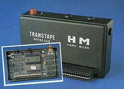
- Transtape
- Transtape Layout, thanks to Jose Leandro
Manual
Downloads
- Transtape-ROM.zip (Transtape ROM)
- Transtape (eagle).zip (Transtape files for Eagle)


