Translation note : Cassette = Tape.
Recording a sound
A sound is recorded by making a measurement of the amplitude of the sound at regular intervals which are defined by the sampling rate and to a vertical resolution (between the lowest and highest points on the wave) that is called the bit-depth. The act of taking the measurement is often called sampling and each measurement unit is called a sample. A file which contains samples is often called a waveform, sound sample, audio sample, etc.
The sampling rate defines the rate/frequency at which the measurements are taken. The higher the sampling rate, the faster/more frequently the measurements are taken, and the higher the maximal frequency that can be represented by the signal. Conversely, the lower the sampling rate, the slower the measurements are taken, and the maximal frequency that can be stored is lower. The sample rate is described by the "Hz" unit of measurement. The "Hz" unit of measurement means "per second". Therefore, a sampling rate of 44100 Hz, a.k.a. 44.1 kHz, means that 44100 measurements are taken each second (in other words, one measurement every 1/44100 th of a second).
If the sampling is too low, then changes in the sound which occur between each measurement will not be measured. Because higher audio frequencies are defined by oscillating more rapidly, this means that lower sampling rates can store only lower frequencies. Therefore, the faster the measurements are taken, the more accurate the recording will be, and thus the higher the quality of sound that can be recorded. Of course, at high sample rates, because there are many more measurements taken, the resulting size of the file (containing the audio data) can be large.
As should be familiar to CPC users with a little technical knowledge, a sample that uses 8-bits for storage can represent 256 distinct amplitude levels, and a sample which uses 16-bits for storage can describe 65536 distinct amplitude levels. The higher the number of bits used by each sample for storage, the larger the range of distinct amplitude levels that can be represented. Therefore, the higher the number of bits used by each sample for storage, the higher the quality of sound that can be recorded. Moreover, the number of bits is directly related to the dynamic range of the resulting signal; that is, how much of a difference there is between the quietest and loudest sounds that it can represent. 16-bit signals provide a nominal 96 dB of dynamic range.
What settings should you use?
All modern sound cards should support 8-bit and 16-bit samples and sample rates of 22050 Hz and 44100 Hz. Some sound cards will support a greater range of recording rates which can be lower and higher than these values. The familiar format of CD audio uses a sampling rate of 44100 Hz and a bit-depth of 16-bits. These values are more than adequate to represent almost all real-world signals for listening by humans - and also, conveniently, are fine for Amstrad tapes, too! In fact, in theory, because the standard Amstrad tape routines have a maximal frequency of 2500 Hz, settings as low as 8000 Hz and 8 bits would probably be fine. However, you will probably want to use higher settings, just in case and/or to keep in line with more common formats such as CD audio, especially if you intend to archive your recordings.
For samp2cdt, you should save the file as "PCM" ("Pulse Code Modulation"). This is a uncompressed, unencoded storage representation. Each sample is a single measurement of the amplitude of the sound taken at a measurement point in time. Other representations such as "ADPCM" ("Amplitude Delta Pulse Code Modulation"), encode or compress the data to reduce the size of the audio file. Samp2cdt can't understand these representations, so please use "PCM" only.
Illustrations and explanations of digital audio
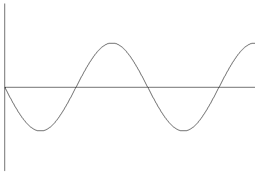
Fig 1. An amplitude/time graph showing the waveform of the original sound
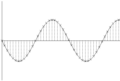
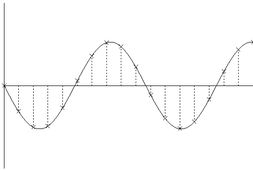
Fig 2. An amplitude/time graph showing the waveform of the original sound. The crosses indicate the amplitude measured at each sample time and the dotted lines indicate the the time of each measurement. The duration of time between each dotted line, defined by the sample rate, is equal to the duration of a sample. From this it can be seen that each sample has a finite and equal duration.
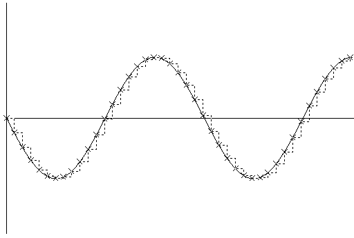
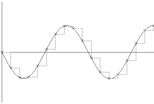
Fig 3. An amplitude/time graph showing the waveform of the original sound. As in Fig 2, the crosses indicate the amplitude measured at each sample time. The dotted line shows the waveform generated by sampling. The final value of each sample is defined to be the amplitude measured at the time of measurement.
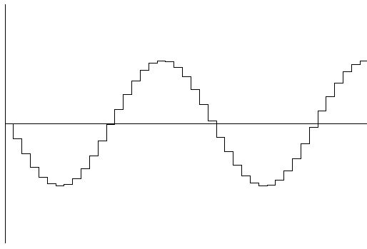
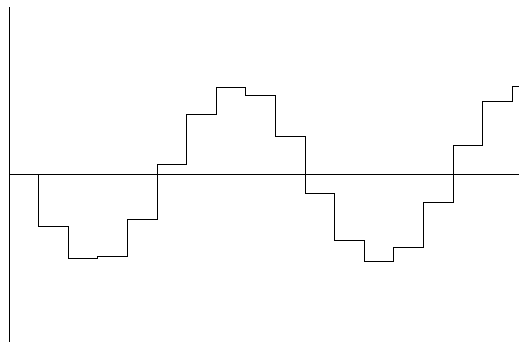
Fig 4. An amplitude/time graph showing the sampled waveform. This waveform was generated at a high sample rate, and therefore the resulting waveform has a shape which is similar to the original. This waveform is the type you can see in a audio recording program like Goldwave. Note, however, that this distinctively square signal is not what would be output by any barely decent sound-card! Audio hardware has built-in filters to smooth waveforms as they are converted from digital to analogue.
Fig 5. An amplitude/time graph showing the waveform of the original sound. As in Fig 2, this graph shows the amplitude of each measurement, and the dotted line indicates the time of measurement. This graph was created using a low sample rate. Notice that the time between each measurement is longer compared to Fig 2.
Fig 6. An amplitude/time graph showing the waveform of the original sound. As in Fig 3, the crosses indicate the amplitude measured at each sample time, and the dotted line shows the waveform generated by sampling. This graph shows the resulting waveform generated using a low sample rate.
Fig 7. An amplitude/time graph showing the sampled waveform. As explained in the note for Figure 4, this is only a visual representation of the digitally stored audio, not of the signal that would be output by any competent audio card. However, it does illustrate how low sampling rates reduce the bandwidth of frequencies: This waveform was generated at a low sample rate, and therefore the resulting waveform is much more coarse compared to Fig 4. Notice that although the general shape is similar to the original waveform, much of the smoothness is is lost between the time of each measurement. The loss of smoothness also means loss of information: the lower the sampling rate, the more information is lost; in other words, the maximal frequency that the signal can represent is lower. Similarly, lower bit-depths mean that the signal is less accurate, and in extreme cases can generate audible noise. Therefore, to record a sound, it is best to use relatively high sampling rate and bit-depth; CD audio's 44.1 kHz and 16 bits should be more than adequate for most uses, especially storage of CPC cassettes.
Notes:
1. The "Nyquist theory" states that in order to accuratly record a sound of a known frequency, you must use a recording frequency which is more than twice that frequency (note "more than", not equal to). Example: to record a sound of 3000 Hz, you must record using >6000 Hz. If you use a lower sampling rate (e.g. 5000 Hz), frequencies less than or equal to half of the sampling rate cannot be properly represented and will be altered into lower-sounding frequencies. Most Amstrad loaders are between 300 to 2500 Hz, therefore you should use a recording sample rate of >5000 Hz. It is recommended to use one of the common sample rates. e.g. 22050 Hz (22.05 Khz) or 44100 Hz (44.1 Khz).
2. There are two different representations to store the amplitude of the sample in a PCM audio file: unsigned or signed.
- A 8-bit unsigned sample has values between 0 and 255. In this range, 0 represents a low amplitudes, 255 a high amplitude, and the amplitudes increase linearly from 0 to 255.
- A 8-bit signed sample has values between -128 and 127. In this range, -128 represents a low amplitude, and 127 high amplitude, and the amplitudes increase linearly from -128 to 127.
Both methods can represent the same data, just in different ways (techies will be able to compare this to their knowledge of Z80 assembly), so there is no advantage to using either. The original reason for the two methods is due to the original method to playback the sound. Modern sound cards can play audio stored in both ways. Note that both (albeit more obvious in the latter) share a feature typical of binary-encoded numbers: there is no exact 'centre' value, because the total number of possible values is even. In the context of audio, this means that, if the signal spanned the entire range, its centre (average) would be slightly off-zero (in this case, below), which is known as a DC offset. However, even if this did occur, it would be negligible and certainly not audible by humans!
Duplication of cassettes
When the writing of a program is completed a "master" cassette is created. This cassette contains a audio representation of the computer data.
The master cassette is then duplicated, using a machine, onto many blank cassettes. These cassettes are packaged with instructions and distributed.
It is also easy to make a copy of a cassette if you have a twin cassette system, where one cassette unit will play the sound and the other will record. A first generation copy taken from a original cassette could be considered a copy of a copy of the master cassette.
Each time a cassette is copied however, additional noise may be introduced into the copied version. This noise is a mixture of noise from the original, and noise created by the machine making the copy. Therefore the sound on any cassette contains a mixture of noise and the sound of the computer data.
A loader on the computer must therefore be able to identify the actual sound of the data from other sounds that are on the cassette. If it can't do this, then there will be loading errors.
If you are transfering a cassette using samp2cdt, then you are advised to use an original (i.e. a cassette created directly from a master cassette), or a first generation copy (i.e. a cassette copied from an original).
Loader
A "loader" is the name given to a program that reads data from cassette into the computer memory.
There is a "system" loader which is built into the Amstrad CPC ROM. This loader is activated when the computer is in cassette mode (note 1), and it can only understand one specific computer audio sound, the audio sound of the Amstrad CPC system data-blocks.
To read other loading systems (e.g. a fast-loader), there must be a program on the cassette (a "pre-loader" or "boot loader" or sometimes refered to as "loader"), stored using the Amstrad CPC system loader, which when executed will be able to understand and load fast-loader data.
This loader program is usually stored immediatly before any fast-loader blocks, and takes over from the system loader to load the remaining fast-loader blocks.
|program for fast-loader| |fast-loader block(s)|
So when a cassette is loaded the following occurs:
1. system loader recognises and loads "program for fast-loader". 2. "program for fast loader" takes control and loads the data from the fast-loader block(s) into computer memory 3. when loading has completed, the program is executed.
Notes:
1. a CPC without a disc interface (e.g. a CPC464, CPC464+ or KC Compact) will start-up in cassette mode. For a CPC with a disc interface attached (or internal), you must type |TAPE to enter cassette mode.
You can test if the computer is operating in cassette mode by typing RUN". If you see "Press PLAY then any key", then the computer is operating in cassette mode. If there is an error, then the computer is not operating in cassette mode.
Amstrad cassette hardware
Reading
The audio from the cassette is read from a cassette player through the Amstrad's cassette electronics.
The Amstrad's cassette electronics converts the amplitude of the sound (a analogue signal) into a "0" or "1" measurement (a digital signal). This measurement can then be read from bit 7 of port B of the PPI 8255 IC.
Fig 8. This image shows the conversion of the audio waveform from the cassette into the digital representation by the Amstrad's cassette electronics. i.e. audio waveform (on cassette) -> Amstrad's cassette electronics -> 0 and 1 measurements
The resulting measurements can be read using the following Z80 instructions:
ld b,&f5			;; I/O port address for PPI 8255 port B
				;; (PPI 8255 port B is operating as input.)
in a,(c)			;; read port B inputs
and %10000000			;; isolate bit 7 which contains the measurement.
This measurement is *not* the actual state of a data-bit, but represents a low ("0") or high amplitude ("1"). In this document, the value of this measurement will be refered to as a "high" ("1") or "low" ("0") level.
Notes:
1. The CPC464 and CPC464+ have a cassette player built in. To connect a cassette player to the CPC664, CPC6128 or KC Compact then you must use a lead. 2. It is not known exactly how the amplitude of the sound from the cassette corresponds to the final "0" or "1" measurement.
samp2cdt uses a crude method to perform this conversion.
For a 8-bit signed sample:
- if the amplitude is 0..127, then the final measurement will be "1".
- if the amplitude is -128..0 then the final measurement will be "0".
Writing
A waveform is written to cassette using bit 5 of port C of the 8255 PPI IC. The waveform can only be defined by a high or low level, defined by the state of bit 5, which is then converted by the Amstrad's cassette electronics into a final output amplitude which is recorded onto cassette.
A high level can be written using the following Z80 instructions:
ld b,&f6		;; I/O port address for PPI 8255 port C
			;; (PPI 8255 port C is operating as output.)

set 5,a			;; set cassette write output to high level
out (c),a		;; output level
A low level can be written using the following Z80 instructions:
ld b,&f6		;; I/O port address for PPI 8255 port C
			;; (PPI 8255 port C is operating as output.)

res 5,a			;; set cassette write output to low level
out (c),a		;; output level
The amplitude of the output waveform is not amplified, therefore if you wish to record the cassette audio direct from an Amstrad you will need to amplify the waveform.
If the state of bit 5 is changed at a fixed frequency, then the graph of the state of bit 5 over time will be a square wave. However, the resulting audio written on the cassette will not be a perfect square wave because nature will attempt to convert the waveform into a sine wave. Loading system audio waveform
Every loading system on the Amstrad uses a serial bit-stream. i.e. a single bit of information is read at a time.
This serial bit-stream is grouped into blocks of audio sound.
Every loading system uses a basic structure to describe each audio block in the following order:
|pilot|sync|data|trailer|
pilot
This is also refered to as "leader" by some documents.
This is constructed from a repeated waveform often with a fixed number of repetitions defined by the loading system.
The shape of the waveform is known by the loader program and this is used to identify the pilot waveform from other waveforms that may be present (e.g. noise).
The pilot is often long, so that the loader doesn't need to see the start of the pilot waveform in order to load the block.
The loader program will test the incoming waveform, checking it against the parameters defined for the pilot, before the waveform is accepted as the pilot waveform. (e.g. the number of repetitions must be some defined minimum value). The incoming waveform must fall within these specifications otherwise the waveform is not accepted as a pilot waveform.
sync ("synchronisation")
The sync is a waveform which is different to the pilot, and this defines the end of the pilot and the start of the data. When this sync has been detected, the loader knows that there is data following, and that the loader is always at the same point in the data stream. i.e. the loader program is synchronised to a specific point in the data waveform.
data
This is the actual data which is composed of waveforms defining "0" and "1" data bits.
The first element of the data may be a marker or id which may, for example, indicate the type of data in the block or the number of the block.
The remaining bits will define the data and zero or more checksums.
The whole data may consist of a single block with a single location and length (e.g. one block for a screen another for data), or multiple blocks each with their own location and length. (e.g. one block for screen and data)
The location and lengths of the blocks may be in the data stream itself, or they may be in a preceeding block, or may be hard-coded into the loader program.
trailer
The trailer always follows the data. Some loaders may not have a trailer. The two main purposes of the trailer are to ensure that the waveform of the last data bit in the data is constructed correctly and to provide some time in which the loader can prepare for the next block.
The exact definition of the loading systems's audio waveform is defined by the loader program.
samp2cdt has a number of decoder algorithms which recognises the audio waveform of various loading systems. These decoders read the waveform using a similar method to the loader program itself. These decoders have been created by examining the instructions of each loader program and the graph of the waveform in a sound recording package.
Example of a typical loading system
The data on cassette actually consists of changing 0 and 1 levels. (a "level" is a magnitude of a value). The loader measures the time between each "level transition" where a "level transition" is the change from a "0" to a "1" level or the change from a "1" to a "0" level. The level can be timed using the following Z80 instructions:
;; - keep testing the state of bit 7 of PPI 8255 port B
;; - update the counter to record the number of tests done
;; - when bit 7 of PPI 8255 port B changes state, stop testing.
;; counter will hold the total number of tests made.
;;
;; B = &F5 (I/O address of PPI 8255 input port B)
;; C = previous data read from PPI port B
ld d,0              ;; initialise count to 0
.loop inc d         ;; increment count
in a,(c)            ;; read input to PPI 8255 port B
xor c               ;; exclusive-or with previous data read from PPI 8255 port B
and %10000000       ;; isolate bit 7
;; if result is 0, then the state of bit 7 that has
;; been read is the same as the previous state. i.e. bit 7 has not changed state.
;; if result is not 0, then the state of bit 7 has changed.
;; e.g. if bit 7 was previously 1, it is now 0. if bit 7 was previously 0, it is now 1.
jr z,loop
;; when execution reaches here we know that bit 7 has changed state and D
;; contains the number of tests.
Loader operation
The loader generally operates in this way:
1. Time a wave. Is the duration of the wave within the minimum and maximum duration required for the pilot. If yes, go to 2, else go to 1.
2. We might have seen a wave from the pilot signal. time a wave. Is the duration of this wave within the minimum and maximum duration required for the pilot. If yes, increment number of waves seen, go to 2, else go to 1.
3. Have we seen the minimum number of pilot waves? Yes, go to 4, else go to 2. 4. time a wave. Is the duration of the wave within the minimum and maximum duration required for the sync? 2. Each Z80 instruction takes a finite time to execute. The execution time depends on the computer. If the timing of the Z80 instructions used by the test algorithm is known and predictable, then the time for each test can be calculated. Now, since the count represents the number of tests made before the condition is true (i.e. bit 7 changes state), the total time for the condition to be true, is the sum of the time for each test made. If each test always takes the same time, then the total time is the number of tests multiplied by the time for one test. In the Amstrad computer, all Z80 instructions execute in multiples of 1us (microsecond) regardless of their location in RAM. This fact simplifies this calculation. Checksum
A "Checksum" is used to verify the loaded data.
A Checksum is the result of the "checksum calculation" made on a block of data. The actual calculation can be different depending on the method chosen.
There are two "Checksum"s.
1. a stored "Checksum".
This is the result of the "checksum calculation" calculated from the correct data. This is then stored with the data (e.g. before or after the data) when the master cassette is created. 2. a calculated "Checksum".
This is the result of the "checksum calculation" calculated from the data read from the cassette. After the calculation is complete it is compared against the stored checksum.
The stored and calculated "Checksums" are initialised with the same initial value and calculated using the same algorithm. Therefore, if the stored checksum matches the calculated checksum, it is assumed that the loaded data is identical to the original data. The data is verified to be correct.
If the stored checksum doesn't match the calculated checksum, then there has been a error. One or more bit's of data is incorrect. The checksum is designed to detect errors only, and often it is not possible to know which bit or bits of data is incorrect and in this case it is not often possible to correct the errors to reproduce the correct data.
A loader which has a checksum therefore is better than a loader that doesn't have a checksum, because the checksum will verify that the data is correct or incorrect.
With a loader which doesn't have a checksum, you have no way to verify the data, and therefore you can't guarantee that the data is identical to the original.
In this case, the only way to test that the data is correct is to make multiple transfers of the program and test each thoroughly (e.g. if the program is a game, you would play the game to the end), checking for graphic corruption and bugs. If all of the transfers operate the same, then you can assume that the data is correct.
Various Audio file formats
There are numerous Audio file formats, each of which can store audio, but each has it's own structures and representation for the data.
The "format" of a file describes the internal structure, order and encoding of the data within the file.
Here is a list of the audio file formats supported by samp2cdt:
- Windows Wave file (a file which has the ".wav" file extension) is the common file format used for audio sounds on computers running "Windows".
- A Voice Wave file (a file which has the ".voc" file extension) was created by Creative for the original Soundblaster ISA sound card. This file format is used by the original voc2tzx utility which samp2cdt was developed from.
- A Audio Interchange file (a file which has the ".aiff" or ".aif" file extension) is the common file format used for audio sounds on the Mac computer.
- A file which has the ".iff" file extension is the common file format used for audio sounds by the Amiga computer.
