Description
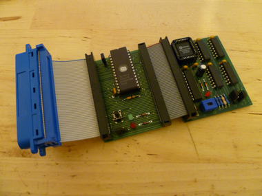
The LowerROM Board allows you to replace the internal OS Firmware and BASIC without making any internal modifications. The upper part of ROM 0 contains the BASIC and can be replaced using many standard ROMBoards. The lower portion of ROM 0 contains the OS Firmware, but because it is mapped to a different address range, it is not a feature usually found on normal ROMBoards. This device solves that problem.
Warning / Disclaimer
Although I have taken the utmost care preparing this documentation, I do not guarantee that it is error free and I accept no responsibility for damage to anyone’s CPC, other personal equipment or injury inflicted on you or others.
The Circuit
Schematic diagram to come later....
Using the LowerROM Board
The LowerROM Board needs to be connected as the first device to the CPC, if any further devices such as a ROMBoard, DDI-1 or RAM expansion are to be added, these MUST be connected behind the LowerROM Board. This is because the 50 way output connector of the LowerROM Board is NOT the same as the CPCs expansion port. ROMDIS has been interrupted to allow both the LowerROM Board and further external ROMBoards to work together without clashing.
The LowerROM Board can hold two alternative OS/BASIC images, giving the CPC a total of three Firmware versions to choose from.
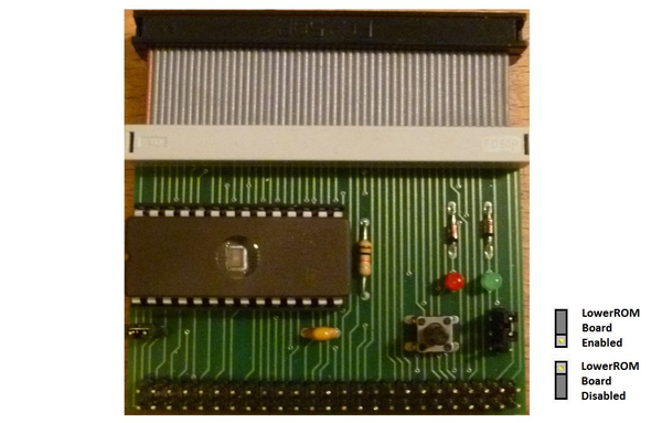
The 2 pin jumper on the left selects which of the external Firmware versions should be used. Remove this jumper to select Firmware 2 of the LowerROM Board.
The 3 pin jumper enables / disables the LowerROM Board as shown in the diagram below. When the LowerROM Board is enabled, the green LED will be lit. When disabled the red LED is lit.
The button on the right is a reset switch for the CPC.

