Preface
This document shows pinning list, wiring diagrams and signal descriptions found on a CPC6128.
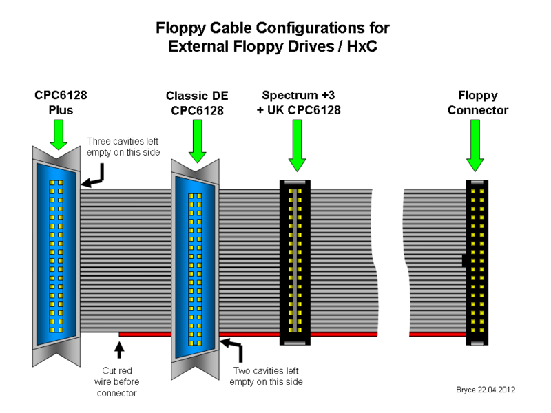
Multi-Adaptor Cable for External Floppies / HxC emulator
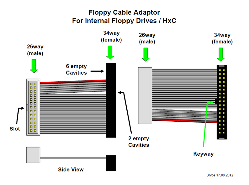
Adaptor Cable for Internal Floppies / HxC emulator
This cable assumes that the drive has been set to DS0 / ID0 and provides a ready signal. For the HxC not a problem, just a simple jumper setting, for floppies this may involve making some mods to the drive.
I've shown the cable from several views to highlight the fact that the connectors don't face the same way on the cable.
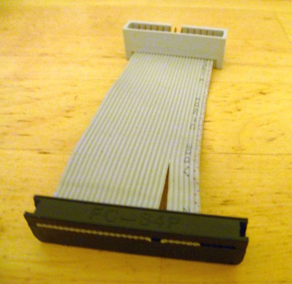
First crimp the 26way cable as shown in the diagram. Then split the first 6 wires starting from the side of the red wire. These 6 wires need to be shifted 2 cavities further over before being crimped into the 36way connector. Wire 26 goes directly to pin 34 of the floppy connector. Make sure the keyways / orientation slots of both connectors are as shown in the diagram. The cable needs no bridges, switches or anything else. When you are finished, you should have a cable looking something like this:
Signal assignment on connectors
Standard floppy connector 34pin
Floppy    | Signal description
connector | for standard floppy connector 34pin
----------+---------------------------------------------------
  1..33   | GND
  2       | /DS (density select 1=low desnity / 0=high density
  4       | NC
  6       | NC
  8       | /IND  index
 10       | /MED0 motor enable drive 0
 12       | /DRV1 drive select 1
 14       | /DRV0 drive select 0
 16       | /MED1 motor enable drive 1
 18       | /DIR  direction select
 20       | /STEP head step
 22       | /WDAT write data
 24       | /WGAT write gate
 26       | /TRK0 track 0
 28       | /WPT  write protect
 30       | /RDAT read data
 32       | /S1   side 1 select
 34       | /RDY  ready (or /DSKCHG) depending on model or drive configuration
CPC-CD201 (internal floppy 26pin connector)
CPC-CD201 | Signal description
          | for CPC internal floppy 26 pin connector
          | (numbering from Amstrads repair manual)
----------+---------------------------------------------------
  1..25   | GND
  2       | /IND  index
  4       | /DRV1 drive select 1
  6       | NC
  8       | /MED1 motor enable drive 1
 10       | /DIR  direction select
 12       | /STEP head step
 14       | /WDAT write data
 16       | /WGAT write gate
 18       | /TRK0 track 0
 20       | /WPT  write protect
 22       | /RDAT read data
 24       | /S1   side 1 select
 26       | /RDY  ready (or /DSKCHG) depending on model or drive configuration
CPC-PL-9 (external floppy 34pin centronics connector)
CPC-PL-9 | Signal description external
         | for CPC external floppy 34 pin centronics connector
         | (numbering from Amstrads repair manual)
---------+--------------------------------------------------
 2..34   | GND
33       | +5V
31       | +5V
29       | +5V
27       | /IND  index
25       | NC
23       | /DRV1 drive select 1
21       | +5V
19       | /MED1 motor enable drive 1
17       | /DIR  direction select
15       | /STEP head step
13       | /WDAT write data
11       | /WGAT write gate
 9       | /TRK0 track 0
 7       | /WPT  write protect
 5       | /RDAT read data
 3       | /S1   side 1 select
 1       | /RDY  ready (or /DSKCHG) depending on model or drive configuration
Pinning translation between different connectors (CPC-PL-9, Centronics 36pin, Floppy connector 34pin)
Translation from CPC-PL-9 via Centronics 36 pin connector to floppy connector 34pin
===================================================================================
(flat cable / crimp variant view)

                          +---+---+---+---+---+---+---+---+---+---+---+---+---+---+---+---+---- GND
                          |   |   |   |   |   |   |   |   |   |   |   |   |   |   |   |   |
Floppy connector 34pin   33  31  29  27  25  23  21  19  17  15  13  11  09  07  05  03  01  NC
Centronics 36pin         18  17  16  15  14  13  12  11  10  09  08  07  06  05  04  03  02  01
Amstard CPC-PL-9         02  04  06  08  10  12  14  16  18  20  22  24  26  28  30  32  34  NC
                       **++**++**++**++**++**++**++**++**++**++**++**++**++**++**++**++**++**++
Amstard CPC-PL-9       01  03  05  07  09  11  13  15  17  19  21  23  25  27  29  31  33  NC
Centronics 36pin       36  35  34  33  32  31  30  29  28  27  26  25  24  23  22  21  20  19
Floppy connector 34pin 34  32  30  28  26  24  22  20  18  16  14  12  10  08  06  04  02  NC
                        |   |   |   |   |   |   |   |   |   |   |   |   |   |   |   |   |   |
                        |   |   |   |   |   |   |   |   |   |   |   |   |   |   |   |   |   +-- NC
                        |   |   |   |   |   |   |   |   |   |   |   |   |   |   |   |   +------ +5V
                        |   |   |   |   |   |   |   |   |   |   |   |   |   |   |   +---------- +5V
                        |   |   |   |   |   |   |   |   |   |   |   |   |   |   +-------------- +5V
                        |   |   |   |   |   |   |   |   |   |   |   |   |   +------------------ /IND
                        |   |   |   |   |   |   |   |   |   |   |   |   +---------------------- NC
                        |   |   |   |   |   |   |   |   |   |   |   +-------------------------- /DRV1
                        |   |   |   |   |   |   |   |   |   |   +------------------------------ +5V
                        |   |   |   |   |   |   |   |   |   +---------------------------------- /MED1
                        |   |   |   |   |   |   |   |   +-------------------------------------- /DIR
                        |   |   |   |   |   |   |   +------------------------------------------ /STEP
                        |   |   |   |   |   |   +---------------------------------------------- /WDAT
                        |   |   |   |   |   +-------------------------------------------------- /WGAT
                        |   |   |   |   +------------------------------------------------------ /TRK0
                        |   |   |   +---------------------------------------------------------- /WPT
                        |   |   +-------------------------------------------------------------- /RDAT
                        |   +------------------------------------------------------------------ /S1
                        +---------------------------------------------------------------------- /RDY

**/++ Flatcable signal
Wireing diagrams
External floppy connector CPC-PL-9 to standard floppy connector 34pin
External floppy connector PL-9 to standard floppy connector 34pin
=================================================================
(flat cable / crimp variant view)

Note: Disconnect wire 03-35-32 /S1 if you use a side selector switch
      which is connected to the floppy drive.

PL9 CEN PCF SIGNAL
 01  36  34 /RDY
 02  18  33 GND
 03  35  32 /S1
 04  17  31 GND
 05  34  30 /RDAT
 06  16  29 GND
 07  33  28 /WPT
 08  15  27 GND
 09  32  26 /TRK0
 10  14  25 GND
 11  31  24 /WGAT
 12  13  23 GND
 13  30  22 /WDAT
 14  12  21 GND
 15  29  20 /STEP
 16  10  19 GND
 17  28  18 /DIR
 18  10  17 GND
 19  27  16 /MED1
 20  09  15 GND
 21  26  14 NC
 22  08  13 GND
 23  25  12 /DRV1
 24  07  11 GND
 25  24  10 NC
 26  06  09 GND
 27  23  08 /IND
 28  05  07 GND
 29  22  06 NC
 30  04  05 GND
 31  21  04 NC
 32  03  03 GND
 33  20  02 NC
 34  02  01 GND
 --  19  -- NC
 --  01  -- NC
Internal floppy connector CD201 to standard floppy connector 34pin
Internal floppy conntector CD201 to standard floppy connector 34pin
===================================================================
(flat cable / crimp variant view)

Note: Disconnect wire 24-32 /S1 if you use a side selector switch
      which is connected to the floppy drive.

CD201 PCF SIGNAL
   26  34 /RDY
   25  33 GND
   24  32 /S1
   23  31 GND
   22  30 /RDAT
   21  29 GND
   20  28 /WPT
   19  27 GND
   18  26 /TRK0
   17  25 GND
   16  24 /WGAT
   15  23 GND
   14  22 /WDAT
   13  21 GND
   12  20 /STEP
   11  19 GND
   10  18 /DIR
   09  17 GND
   08  16 /MED1
   07  15 GND
   06  14 NC
   05  13 GND
   04  12 /DRV1
       11 GND
       10 NC
   03  09 GND
   02  08 /IND
   01  07 GND
       06 NC
       05 NC
       04 NC
       03 NC
       02 NC
       01 NC
Issues
Floppy drive
Floppy drive issues
===================
* This cables work for drive which are jumpered as drive 1/DS1. This is normally the default selection on drive delivery.
* Make sure you find a drive which has the possibility to generate a ready signal instead of a disc change signal.
Disk issues
Disk issues
============
If you think about to use a HD drive, make sure to close the HD detection hole on your disk.


