Description
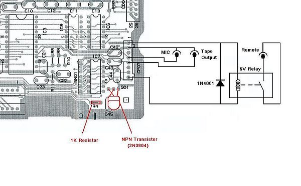
The connection diagram below will allow you to connect a tape player or other audio recording device / PC soundcard to a CPC6128+ which will then act as a Tape input and output.
The header connector CP07 can be found in the bottom right corner of the main PCB. Ensure that the relay and diode are mounted in such a way that none of their pins can come in contact with any metal within the CPC housing or any other part of the main PCB.
The transistor and resistor shown in red below, must be added to the main PCB, the pad positions should be present but unpopulated.
Note: The pinout of the 2N3904 is not identical to the original transistor used by Amstrad and should be mounted as shown below with the Base and Collector pins swapped!
Should you be able to source the original transistor (now sold as 2SC1815) these pins should not be swapped.
If you're getting errors while trying to load or save files, you can find the error code descriptions here: Read Error Codes
