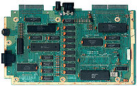
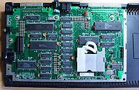
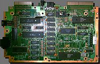
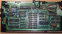
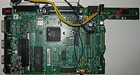
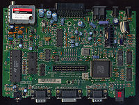
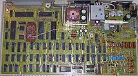
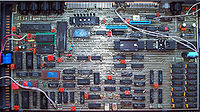
CPC464 version 1 (original)
- Size: ??? x ??? mm
- Board: PT NO Z70100, without any "MCnnnn" code, Copyright 1983
- Original version. Big mainboard, old Gate Array (with cooling plate). Real wires going to keyboard.
- Board: PT NO Z70100, MC0001A, Copyright 1983
- Keyboard connector now has two rows of soldering points (maybe intended to allow to use different connectors)
- Board: PT NO 270100, MC0001A, Copyrigh 1983
- This one is labelled 270100, not Z70100.
- And it says "Copyrigh", not "Copyright"
- Unlike all other boards, its font has slashed zeroes.
- Board: Prototype with Gate Array Simulator (more pictures)
- The Gate Array Simulator board (mounted on top of the mainboard, and almost having the same size as the mainboard) contains four 8K EPROMs, and a Gate Array prototype made of several logic chips. In later versions these evolved into a normal 28pin 32K ROM chip, and the custom 40pin Gate Array chip.
CPC464 version 2 (new gate array)
- Size: ??? x ??? mm
- Separate soldering points for old and new Gate Array (with changed pin-outs).
- New connector for fragile membrane keyboards (still has optional soldering points for fitting the old more robust keyboard).
- Board: PT NO Z70200, MC0002D, Copyright 1984
- Board: PT NO Z70200, MC0002C, Copyright 1984 with MS0043A daughterboard (more pictures)
- The Spanish CPC472, with nonfunctional 8K RAM on the daughterboard
CPC464 version 3 (medium-sized)
- Size: ??? x ??? mm
- Medium sized mainboard. Same components as previous version, but arranged more tightly. Joystick/stereo moved to left side.
- Can be optionally fitted with Amphenol connectors (instead of Edge connectors, as far as known, this option was never used for the 464). The screw-holes have contacts for optional shielding-plate (this option was used in german Schneider models).
- Board: PT NO Z70374, MC0044A
- Board: PT NO Z70375, MC0044D
- Mostly same as Z70374. The 3 resistors in upper-right are arranged differently, different cassette connector installed, tinned GND fields.
- Board: PT NO Z70378, MC0046A
- Additional loops near cassette, monitor, keyboard connectors. Used in german Schneider models.
CPC464 version 4 (cost-down)
- Size: ??? x ??? mm
- Board: PT NO Z80329, MC0099A, Copyright 1988
- Tiny mainboard. Uses 100pin SMD Gate Array (combines the old Gate Array, CRTC, and some FDC/DRAM/RESET logic in one chip).
CPC664
- Size: ??? x ??? mm
- Board: PT NO Z70205, MC0005A
- 8pin FDC Data Separator
- Board: PT NO Z70205, MC0005B
- Another 664 version, found in german Schneider CPCs (but might be also used in other countries?)
- This board version typically includes a small patch: A resistor soldered between Pin9 (A0) and Pin14 (/CASADDR) of IC105. The patch is also seen here. The resistor is labeled as R160 in the schematic, but isn't labeled on the PCB, so it was apparently added after designing the PCB.
CPC6128 version 1 (8pin data separator, solder points for old and new gate array)
- Size: ??? x ??? mm
- Board: PT NO Z70210, MC0009A
- Separate soldering points for old and new Gate Array (as far as known, the old Gate Array was never used in 6128 though, only in 464).
- 8pin FDC Data Separator.
- Can be fitted with Amphenol connectors (as used in german cpcs) (instead of edge connectors).
CPC6128 version 2 (24pin data separator, solder points for new gate array only)
- Size: 320x155mm
- Board: PT NO Z70290, MC0020B, R1706-94HB, Copyright 1985
- Can be fitted with Amphenol connectors (done in germany) (instead Edge connectors).
- Uses 24pin FDC Data Separator.
- Here's also another picture.
- Board: PT NO Z70290, MC0020I, 94V.0-FR-4, Copyright 1985
- Board: PT NO Z70290, MC0023D, 94HB-R1706, Copyright 1985
- Sold in germany, with Amphenol connectors (and dummy edge-connectors which don't have any contacts, and which are covered by green solder-stop layer), front of mainboard has several vias for giving better contact to shielding plate).
- Note: The board does exists: I do have a CPC with that board, but I've modified it, and putting pictures of modded boards here would look a bit confusing. Does somebody have an unmodded board? --Nocash 23:36, 9 April 2010 (UTC)
- Note: The via in the text makes it easy to misread the part number (it's Z70290, not Z70250).
- Board: PT NO Z70290, MC...?, 94...?
- Looks almost like the above german board, but the "94HB-R1706" is different
- http://www.1000bit.it/scheda.asp?id=30 (not perfect picture quality; and board numbers are hidden under shielding plate and capacitors)
- EDIT: There was a picture of that board - but now it's replaced by better picture, but now showing a totally different 6128 board :-/
CPC6128 version 3 (cost-down)
- Size: ??? x ??? mm
- Board: PT NO Z80330 (1988)
- Uses 100pin SMD Gate Array (combines the old Gate Array and PAL, CRTC, and some FDC/DRAM/RESET logic in one chip).
- Can be fitted with four 64Kx4 RAM chips (or the normal sixteen 64Kx1 RAM chips)
- Printer port consists of 74LS174+74LS175 (instead of 74LS273)
CPC 464+
- Size: ??? x ??? mm
- Board: 2700-016P-3, MC0122D, Copyright 1990
- Same mainboard is used in 464+ and 664+ (though not all components installed in 464+, and with different LK Links. Uses 160pin SMD Gate Array (ASIC).
CPC 6128+
- Size: ??? x ??? mm
- Board: 2700-016P-3, MC0122D, Copyright 1990
- Same mainboard is used in 464+, but with additional components installed (extra RAM chips, FDC chips, Floppy connector, and with different LK Links).
- Uses 160pin SMD Gate Array (ASIC).
- Board: 2700-016P-3, MC0122B, Copyright 1990
- Another version, MC0122B, is shown in the Service Manuals (Plus series, page 5).
- Board: 2700-016P-3, MC0122A, Copyright 1990
- Yet another version, MC0122A, is shown in the Service Manuals (Plus series, page 16).
GX4000
- Size: ??? x ??? mm
- Board: 2700-017P-4, MC0123C, Copyright 1990
- Same chipset as CPC+, but lacks Keyboard, Expansion Port, Printer Port, Tape/Disc Interfaces.
- Additional Scart Connector and TV Modulator.
- Board: 27...?, MC...?, Copyright 1990
- Version without TV Modulator installed, and with IC101 replaced by 4 transistors (used in French models; where the PAL modulator would be useless).
- See this picture (might be same mainboard as above, not sure - the photo doesn't show the boards part number; hidden behind the cartridge slot, one thing that IS different is the K1 vs K3 text near the LED).
- Board: 2700-017P-3, MC0123A, Copyright 1990
- Shown in Service Manuals (Plus series, page 24 and page 32/france).
System Cartridge (BIOS of CPC+) and Game Cartridges
- Size: 51x60 mm
- Board: PT-NO-Z90903-MC0121A
- With custom LKs, and double-sided soldering points.
- Board: PT-NO-Z90903-MS0201A
- With custom LKs, and single-sided soldering points.
- Board: 2700-023P-1
- With hardwired LK1 and LK6, and single-sided soldering points.
DDI-1
Clones
- Size: ??? x ??? mm
- KC Compact (more pictures)
- East german CPC clone
- Size: ??? x ??? mm
- Board: PATISONIC ALESTE 520EX 01.003 (more pictures)
- Russian CPC clone
Notes
- The last letter of the PT NO Znnnnn, MCnnnnX board numbers does not seem to indicate a revision (the boards appear to be identical regardless of that letter, as long as the other digits are same). So, the last letter may indicate the manufacturing date or manufacturing location.
See also
- Amstrad part numbers - Part Numbers for PCBs and Chips
- Schematics
- Service Manuals - (cost-down 6128 is in the Amendment manual)
Forum
- http://cpcwiki.eu/forum/index.php/topic,678.0.html - CPC Mainboard Versions related


