Description
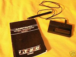
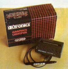
A Lightpen by dk'tronics.
The lightpen was distributed with an art package.
The dk'Tronics lightpen came in two versions.
A version where the art package was put on an ROM located on the interface.
A version where the art package had to be loaded from disc.
The lightpen came in two different casings. One for the CPC464 and one for the CPC6128. The contents however were the same.
Software
The ROM version of the art package was started with the bar command |Lightpen. The art package used an on-screen menu system consisting of 5 menus and 3 sub menus which could be navigated using the lightpen. Each menu offered 3 - 5 large icons to choose the commands. The selected command displayed a square bracket around the icon.
Menus
- Menu 1 - Saving and loading files from disc or tape
- Menu 2 - Clear screen / Calibrate Pen / Next Menu
- Menu 3 - Draw / Fill / Set Colour / Set Pencil / Next Menu
- Menu 4 - Rubber Band / Outline / Set Colour / Set Pencil / Next Menu
- Menu 5 - Circle / Rectangle / Copy (Sub menu) / Text (Sub menu) / Scratch Pad (Sub menu)
Sub Menus
- Copy Menu - Copy & Expand / Shrink
- Text Menu - Vertical Text / Horizontal Text / Set Colour
- Scratch Pad - Screen to Pad / Edit / Pad to Screen
Rubber Band was a method of drawing curves and irregular shapes by defining points on the screen to be joined by a line.
The scratch pad was a simple copy/paste area which could be edited seperately.
The handbook also gave instructions in both BASIC and assembly to use the lightpen within your own programs. A small routine to return the X and Y coordinates which worked in all screen modes:
10 out &1C00, 17 : L=inp(&1F00) : out &1C00, 16 : H=inp(&1F00)
20 L=H*256+L-12292 : Y=L/40 : X=L-Y*40
The value 12292 needed to be slightly adjusted to match the monitor being used. This could also be achieved in software by incorporating a simple manual calibration routine.
Technical
Uses I/O ports: #1C00 and #1F00 (as shown in above BASIC example)
- #1C00 and #1F00 are bad decodings/mirrors of CRTC ports #BC00 and #BF00
- These ports will clash with other hardware (but do work more or less)
- A15=0 doesnt't trigger the Gate Array (which would also require A14=1)
- A13=0 does trigger Upper ROM Bank Number (but the IN's don't cause problems since the ROM bank is write-only, the OUT's do activate bank 16 and 17, but usually don't cause problems since these banks usually contain mirrors of the BASIC ROM)
The Lightpen uses the CRTC /LPEN input on the expansion port.
dk'Tronics lightpen artpackage screenshots
Manual
- Media:DKTronics_Lightpen_Manual.pdf - DK'Tronics User Manual (English)


