Description
This project converts an MP1 into an MP2 (i.e.: adds the 12V output required for the CPC664 and CPC6128). Why? Originally back in the 80's I owned a CPC464 and bought an MP1 for it (MP2s were much more expensive and I had no need for the extra output), but now being the proud owner of a 6128 and having converted the MP1 to composite, I use the MP1 regularly and didn't want the hassle of having a second power supply just for the 12V. So it was time to make an upgrade.
Warning / Disclaimer
This project involves opening and modifying a device which uses 240V AC. If you don't know what you're doing, then leave it to someone who does. Although the modifications do not involve the high-voltage areas of the circuit, extreme caution should be taken at all times and the unit should always be disconnected from the mains supply BEFORE the casing is opened and only re-connected after the case has been closed again.
Although I have taken the utmost care preparing this documentation, I do not guarantee that it is error free and I accept no responsibility for damage to anyone’s MP1/2, shiny new television, other personal equipment or injury inflicted on you or others.
What Is In The MP1?
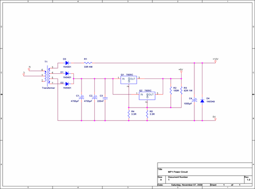
I read a claim somewhere, that the MP1 had the exact same circuitry as the MP2 and that just the socket was missing. Although I've never seen an MP2 in the flesh, I very much doubt that this is the case. For a start, why would Amstrad go to the bother of producing two separate devices, if the only difference was a cheap socket, this wouldn't make financial sense. So I opened up the MP1 and took a closer look at the power circuitry. Here's what I found:
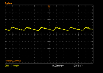
The circuit is basically two supplies, the majority of the circuit comprises of two 7805s in parallel with a few resistors, capacitors and diodes which gives a regulated 5V output. The rest of the circuit is indeed a 12V supply which is required for the TV modulator circuitry, however the supply would not be sufficient to fulfil the 12V requirements of a 6128. Firstly, the 12V output isn't very “clean”, it's a half rectification of an 18V AC signal, with a capacitor and a zener diode to smoothen and regulate things a bit. Here's what the output looks like on the scope:
As you can see, it's all over the place. It oscillates between 12V and 12.7V at around 50Hz, which is ok for the TV modulator, because the MC1377 has its own internal 8.2V regulator, but it's not ideal for the motors in the 6128. This isn't the only issue we have though. The diode used to regulate the 12V signal (D4) is a 1N5349, which is rated at max. 395mA, the modulator circuitry needs around 50mA, which would leave just 345mA for the CPC. Unfortunately the CPC needs around 400mA, so if the CPC were to be connected to this supply, not only would the motors in the disc drive probably not turn, but their attempt to turn would starve the modulator of the amps it needs and the TV picture would most likely flicker in time with the motors attempts. This is obviously not the ideal situation.
The Circuit
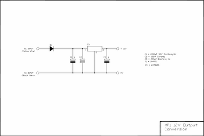
We could of course upgrade this 12V supply and clean up the signal to what the CPC needs, which would be possible, but it's more bother than it's worth. Instead the solution described here adds a second regulated 12V supply in parallel, just for the CPC. With just five components, we can cheaply build a decent 12V regulated supply, which can supply up to 1A, more than double what the CPC needs. Here's what the circuit looks like:
The circuit is pretty simple. D1 makes sure the voltage only flows in the direction we need. The capacitor C1 charges during the positive half of the AC wave and discharges when the current is “missing” during the negative half. This bridges the gaps in the supply. The smaller C2 filters out higher frequency noise in the signal. The 7812 then regulates this signal to a perfect 12V DC which is also buffered at the output with C3. The polarity of the electrolytic capacitors (C1 and C3) must be correct. C2 can be connected in either direction.
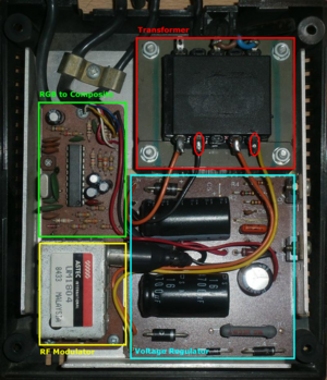
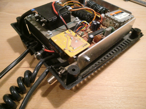
First we need to open the MP1/2. This is done by removing the four screws on the bottom of the unit in each corner. Do not remove the two large screws closer to the centre as these are there to support the transformer, which we don't need to disassemble. The picture below shows the innards of an MP1. In the top right corner you can see the transformer with the regulator circuit board below it. To the left is a small circuit board with the RGB to composite and RF conversion stages.
The two red circles seen on the transformer above show the points where we can access the 18V AC output which we will use to supply our regulator circuit. The yellow lead will be our positive lead, with the black connection as ground. Although this is an AC signal, where polarity is normally not important, in this case we must observe the polarity to ensure that the 12V supply polarity matches the 5V polarity.
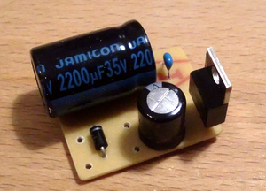
When you have built the circuit it should look something like this:
As you can see, I have kept the layout quite compact, because there's not a lot of space free inside the MP1. In fact the complete circuit board is only 27mm x 34mm. To make things easier, I've placed the 7812 at the edge, so that I can use it's heatsink to mount the circuit. Because the circuit isn't particularly heavy, no further fixing should be needed. The output leads need to be connected to an appropriate socket mounted on the casing, the input leads are soldered directly onto the tabs on the transformer.
Installing The Regulator
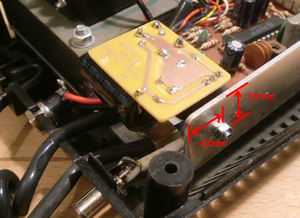
The circuit has been designed to fit in the space above the modulator circuit where there is a small section of MP1 heatsink protruding. This can be used to support the circuit. The circuit board is mounted upside-down bolted to the heatsink and when finished, the circuit board sits nicely in the top corner:
A 3mm hole can be drilled into the heatsink to accommodate the new circuit. Mounting the circuit properly ensures that nothing will short circuit when everything is put back together. The 12V output socket can be mounted in the back plane of the lower housing. When drilling holes in this type of plastic, a wood drill-bit should be used on a slow speed so that the plastic doesn't crack or melt in the process.
IMPORTANT – READ CAREFULLY! If you choose to mount the circuit in a similar manner as I have, using the 7812 heatsink, it should NOT be fixed directly to the MP1 aluminium heatsink! It must be electrically insulated, by using an insulator between the 7812 and the heatsink and a plastic screw/nut, or similar insulating setup. The reason for this is that the 7812/7805 heatsink is internally connected to pin 2. In our circuit, this is connected directly to ground, as is usually the standard. However, as you can see in the MP1 power circuit diagram above, the MP1 5V circuit has two resistors placed between pin 2 and ground (to slightly raise the voltage above 5V), meaning that the heatsink is not as normally expected at 0V, but is actually floating slightly above 0V at around 0.2V. If the 7812 was connected directly to the heatsink it would effectively short-circuit these resistors and mess up the 5V supply. I used a small piece of PCB with a 3mm hole between the 7812 and the heatsink, with a plastic isolating washer. The 7812 is only running at most at around 30% of its maximum capacity, so it shouldn't ever actually heat up and no heatsink is really required in this case.
As we have all learnt from Hollywood Films, even psychopathic bomb-building maniacs seem to stringently follow the standard electrical colour codes (how else would Bruce Willis know that the blue wire is the one that de-fuses the bomb). Although it is not compulsory, I would advise you to use black leads for the ground connections and red for positive connections. It makes it a lot easier to recognise where to connect them without having to check back to the circuit again, and helps to avoid polarity mistakes, that could cost you your treasured CPC. On the 12V output socket, the positive should be connected to the outer ring and the ground to the centre pin.
Resources
The following files are the PCB and component layouts to construct the circuit above:
File:MP1 12V Conversion PCB.pdf - PCB Track Layout)
File:MP2 Power PCB Layout.pdf - Component positions
If you have any further questions regarding this project, please contact me through the Wiki Forum.
Bryce.
