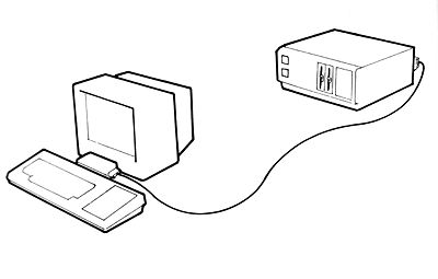
SERIAL INTERFACE USER INSTRUCTION BOOK
AMSTRAD RS232C SERIAL INTERFACE WITH ROM SOFTWARE AND POWER SUPPLY
AMSOFT
A division of CONSUMER ELECTRONICS PLC.
© Copyright 1985 AMSOFT, AMSTRAD Consumer Electronics plc.
Neither the whole nor any part of the information contained herein, nor the product described in this manual, may be adapted or reproduced in any material form except with the prior written approval of AMSTRAD Consumer Electronics plc. (‘AMSTRAD‘). The product described in this manual, and products for use with it are subject to continuous development and improvement. All information of a technical nature and particulars of the product and its use (including the information and particulars in this manual) are given by AMSTRAD in good faith. However, it is acknowledged that there may be errors or omissions in this manual. and a list of details of any amendments or revisions can be obtained by sending a stamped, self addressed envelope to AMSOFT Technical Enquiries.
AMSOFT welcome comments and suggestions relating to the product or to this manual.
All correspondence should be addressed to:
AMSOFT Brentwood House
169 Kings Road
Brentwood Essex
CM14 4EF
All maintenance and service on the product must be carried out by AMSOFT authorized dealers. Neither AMSOFT nor AMSTRAD can accept any liability whatsoever for any loss or damage caused by service or maintenance by unauthorized personnel. This guide is intended only to assist the reader in the use of the product, and therefore AMSOFT and AMSTRAD shall not be liable for any loss or damage whatsoever arising from the use of any information or particulars in, or any error or omission in, this manual or any incorrect use of the product.
Z80 is a trademark of Zilog Inc. AMSDOS, CPC464, CPC664, CPC6128, DDI-1, and FD-1 are trademarks of AMSTRAD. First Published 1985
Written by Roland Perry
Illustrated by Alexander Martin
Electronics and SIO drivers by MEJ Electronics
Programming by AMSOFT:
Printer re-direction, PRESTEL, and TERMINAL by David Radisic
File transfer by Vik Olliver
Concepts by Roland Perry Consolidation and ROM housekeeping by Cliff Lawson
Edited by Ivor Spital
Typeset by KAMSET typesetting graphics (Brentwood)
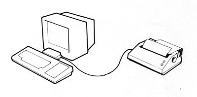
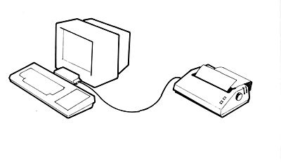
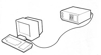
AMSTRAD is a registered trademark of AMSTRAD Consumer Electronics plc. Unauthorized use of the trademarks or word AMSTRAD is strictly forbidden. When you have fitted the AMSTRAD RS232C to your computer, you have the means to communicate with printers, modems, and other computers. Implementing such a link is often regarded as a very mysterious and complicated business, if only because of the serial interface‘s inherent flexibility and versatility. To help you use your AMSTRAD RS232C serial interface, we have provided instructions in the form of ‘magic spells‘. Simply select those spells which are relevant to your application by identifying the accompanying sketches.
A full technical explanation is available in a series of appendices. The examples in these ‘spells‘ are not intended to be an exhaustive survey of all the possible uses of the RS232C. They do represent, however, the majority of applications encountered.
The AMSTRAD RS232C serial interface, and these instructions, are suitable for use with the AMSTRAD CPC464, CPC664 and CPC6128 computers. The AMSTRAD RS232C works equally well with any of these computers. Some of the applications referred to work best with a disc drive, although cassette tape storage is usable as an alternative. Some disc drive applications will require CP/M 2.2 (supplied with both the CPC664, and with the DDI-1 add-on disc system for the CPC464), or CP/M Plus (supplied with the CPC6 128).
When operating in BASIC, the additional commands provided for the RS232C are programmed in a ROM supplied inside the RS232C and are accessed by keywords starting with a bar | symbol. The bar symbol is obtained by pressing
[SHIFT]@
The CP/M commands referred to are supplied on your standard CP/M system disc. The use of a serial interface allows you to connect equipment together using very simple wires up to 50 feet long. It is possible, using a modern, to convert the signals in these wires into a form in which they can be sent almost any distance to another modern, over standard telephone lines. Most equipment manufacturers have agreed the connection details to a standard called ‘RS232C‘. It is also possible to connect devices which conform to the alternative ‘RS423‘ standard.
Spell 1: Connecting the RS232C to your computer
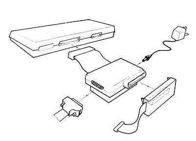
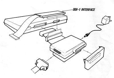
Switch off the computer and remove anything connected to the computer‘s port marked ‘EXPANSION‘ or ‘FLOPPY DISC‘.
Spell 1: Connecting the RS232C to your computer
Switch off the computer and remove anything connected to the computer‘s port marked ‘EXPANSION‘ or ‘FLOPPY DISC‘.
Push the connector plug at the end of the RS232C‘s ribbon cable onto the edge connector of the computer‘s port marked ‘EXPANSION‘ or ‘FLOPPY DISC‘. If required, refit any additional expansion interfaces to the RS232C ‘throgh-bus’ connection. Connect the lead from the RS232C power supply unit, into the small socket on the RS232C it self.
WARNING - ELECTRIC SHOCK NEVER ATTEMPT TO OPERATE THE RS232C POWER SUPPLY UNIT WITH ITS CASE REMOVED.
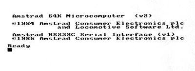
Switch on any additional expansion interfaces, connect the power supply unit on the RS232C to the mains supply, and switch on your computer, in that order. A ‘wake-up‘ message similar to the following will appear on the screen:
Always switch off in reverse order to the above, before disconnecting the RS232C (or any additional expansion interfaces) from the computer.
Always disconnect the RS232C power supply unit from the mains supply socket when not in use.
The serial output lead (the 25-way Chassis-plug) may be connected or disconnected at any time, regardless of power supply considerations.
Spell 2: Cables for connecting a printer (or plotter)
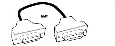
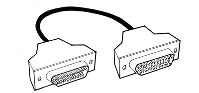
The cable required to connect to a printer (or any other output device) is called a Null-modem cable (NMC). A technical explanation and drawing of the connections required is given in Appendix 1.
A Null-modem cable has Cable-sockets at each end to plug into the Chassis-plugs on the RS232C and the printer. If your printer has a Chassis-socket, then you will also require a converter cable comprising two back-to-back Cable-plugs.
Spell 3: Setting the speed of your printer
It is possible to alter the speed at which characters are transmitted from the RS232C to the printer. The speed is measured by a figure known as the ‘baud rate‘, which has a value of approximately ten l the number of characters per second.
You need to make sure that the RS232C is transmitting at the same speed as the printer is receiving. Do not confuse this serial Interface speed with the speed at which the printer actually prints characters on the paper. If the printer cannot keep up with the rate at which characters are arriving from the serial Interface, then it will send special signals back to the RS232C instructing it to stop sending until the printer catches up. This process is known as ‘flow control‘.
Your printer will probably have some switches (possibly inside its casing) to set its baud rate. The best speed to choose is 9600 baud (approximately 960 characters per second) because that is the default speed of the RS232C.
Spell 4: Setting the speed of the RS232C
The RS232C operates at 9600 Baud unless instructed otherwise.
AMSTRAD BASIC: Use the command: |SETSIO,<baud rate>
CP/M2.2: The baud rate is set when CP/M is loaded. Refer to Appendix 2 (SETUP.COM) for full details on how to alter this power-on configuration.
CP/M Plus: The Baud rate can be changed by the command:
SETSIO, <baud rate>
… or by the command:
DEVICE SIO [<baud rate>]
Examples:
AMSTRAD BASIC: |SETSIO,1200 .... to change to 1200baud.
CP/M Plus: SETSIO 1200 …. or …. DEVICE SIO [1200]
If you require an alternative baud rate, it must be set up every time you reset, the computer or move from BASIC to CP/M, or from CP/M to BASIC. When operating with CP/M Plus, it is possible to program the alternative baud rate as part of the loading process by incorporating the command given above into the ‘PROFILE.SUB‘ file.
NOTE - Under CP/M Plus, if the baud rate is changed by SETSIO, interrogation by use of the command DEVICE will not acknowledge the change.
Spell 5: Setting framing bits (printer)
Characters sent by the RS232C have properties other than simply ‘their speed‘. These properties are: the number of ‘data‘ bits, the number of ‘stop‘ bits, and the type of ‘parity‘. It is not important to understand the exact nature of these properties, but, as with the baud rate, the printer and RS232C should be arranged to match.
Most printers will have switches for these properties. It is not always essential that the RS232C and the printer match exactly; the final test is to try a particular configuration and see if everything works as expected.
The RS232C is set (by default) to 8 data bits, 1 stop bit, and no parity. See Appendix 2 (CP/M) or Appendix 3 (BASIC), for a complete description of the commands required to alter the RS232C framing bits.
Spell 6: Redirecting printer output via the RS232C
Normally, printer output is sent to the parallel Centronics port at the rear of your computer. Having connected and set up the RS232C, the following commands will cause all printer output to be sent via the serial interface:
AMSTRAD BASIC: |SERIAL
CP/M 2.2: STAT LST:=TTY:
CP/M Plus: DEVICE LST:=SIO
When operating with CP/M, it is possible to program this re-direction as part of the loading process. For CP/M Plus, you should incorporate the command given above into the ‘PROFILE.SUB‘ file. For CP/M 2.2, you should use SETUP.COM as described in Appendix 2.
Spell 7: Restoring printer output to the parallel port
Every time you reset the computer or move from BASIC to CP/M, or from CP/M to BASIC, the printer output will be restored to the parallel port. This can also be done using the commands:
AMSTRAD BASIC: |PARALLEL
CP/M 2.2: STAT LPT:=LPT:
CP/M Plus: DEVICE LST:=LPT
Spell 8: Cables to connect Terminal Emulator to a minicomputer
In this manual, a commercial microcomputer that requires a terminal or Visual Display Unit (VDU) in order to operate is also referred to as a minicomputer.
It is possible to connect your computer fitted with RS232C as a substitute for a terminal attached directly to a minicomputer. The cable to use for this will depend on the minicomputer. Use either a Null-modem cable (Cable-socket to Cable-socket) if the minicomputer has a Chassis-plug, or a modern cable (Cable-socket to Cable-plug) if the minicomputer has a Chassis-socket. If in doubt, consult Appendix 1 and the hardware manual of the minicomputer.
Spell 9: Attaching the Terminal Emulator to a minicomputer
The baud rate and framing parameters of the RS232C and minicomputer should agree, as discussed previously when attaching to printers.
The Terminal Emulator is entered by typing:
AMSTRAD BASIC: |TERMINAL
....and is exit-ed by [CTRL] [ESC] Note that the Terminal Emulator ‘inherits‘ whatever keyboard values have been previously set up by BASIC, and also responds to the screen control codes described in the AMSTRAD computer‘s user instruction manual. It will often be convenient to set the [ESC] key to return a standard value by entering:
KEY DEF 66,0,27
Spell 10: Terminal Emulator echo and control codes
The Standard Terminal Emulator sends all key-strokes to the minicomputer, displays all received printable characters, and obeys received control codes. The minicomputer will normally echo the key-strokes sent to it, so that you can see (on the screen of the terminal) what you have typed, character by character. If the minicomputer does not perform such an echo, then it will be necessary for the Terminal Emulator to do it instead. This is achieved by typing:
|HALFDUPLEX
This local echo may be turned off by typing:
|FULLDUPLEX
For diagnostic purposes, it is sometimes convenient for the terminal to display control codes, rather than obey them. The Terminal Emulator can be switched between these two modes by the commands:
|CTRLDISPLAY …. And .... |CTRLACTION
