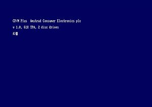
CPM 3.0 (also known as CPM+) was available on the 2nd System_Disk Disc for CPC6128 but there were other implementations available.
Dobbertin's implementation of CP/M+
Graduate Software's implementation of CP/M+ on ROM
Amstrad's implementation of CP/M+
Amstrad distributed CP/M+ on the side 4 of the system discs that came with the CPC6128. It requires a Dk'Tronics compatible ram expansion. It provided 61K TPA. To get 61K TPA, CPM+ uses 'C1' and 'C2' RAM configuration with TPA in the 2nd bank and the CCP, BDOS, BIOS, screen and firmware in the 1st 64KB of RAM. This arrangement allows 61KB useable for programs.
On side 1 of the system discs was CP/M 2.2.
- Amstrad CP/M+ uses Amstrad's "System" format. This is 40 tracks, 1 side, 9 sectors per track numbered &41-&49. Each sector is 512bytes. There are two reserved tracks, then the directory which has 64 entries (which occupies 4 sectors) and then the data area.
- CP/M is booted using an RSX command "|CPM" which is implemented in the Amstrad disc rom (AMSDOS).
- |CPM loads track 0, side 0, sector &41 into RAM at &100-&2ff. This is the boot sector and contains the boot program.
- The boot program then loads the directory from track 2, sector &41.
- The boot program locates a program with extension "EMS".
- This program is loaded into RAM at &c00.
- This is then executed. (EMS contains the BIOS, BDOS and relocates and re-configures the memory. CP/M doesn't use the CP/M 2.2 BIOS from the Amstrad disc ROM.)
Creating a minimal boot disc
Using CPM2.2:
- Use disckit2 to format a vendor format disc
- Use BOOTGEN to put the CPM+ boot sector onto your disc. (Source is CPM+, Destination is your disk).
- Use FILECOPY to put C10CPM3.EMS onto your disc (FILECOPY C10CPM3.EMS. Source is CPM+, Destination is your disk).
- Your minimal CP/M+ disc is bootable.
Using CPM3.3:
- Use disckit3 to format and install the boot sector onto the disc.
- Use PIP to copy C10CPM3.EMS to your disc (B:=A:C10CPM3.EMS)
- Your minima CP/M+ disc is bootable.
Memory layout
- 1st 64KB has Amstrad's XBIOS (callable using 'userf'), CCP, BDOS, BIOS, screen and firmware. Screen is at &4000-&7fff. Firmware is used. AMSDOS is not used.
- &c1/&c2 are used, so that there is common code at &c000-&ffff. This common code has a small BDOS and BIOS. Most of the functions use trampoline code to transition to bank 0 and call into the XBIOS.
- 2nd 64KB has the TPA and the shared code.
a) Page C4 has WBOOT and BDOS jump + &100-&3f00 of the TPA. This calls to functions in Page c7. b) Page C5 has &4000-&7fff of the TPA. c) Page C6 has &8000-&bfff of the TPA. d) Page C7 has &c000-&f2fb of the TPA. From &f2fc to &ffff is the trampoline code which transitions * to 1st bank of 64KB.
Implementing a storage device driver
Using "drvtable" gets the list of DPH addresses for each drive. This is actually fixed at FE2F and is referenced by the XBIOS.
Amstrad have extended the DPH (these appear before the DPH)
- -10,-9 - address of a DD WRITE SECTOR (XBIOS) compatible function
- -8,-7 - address of a DD READ SECTOR (XBIOS) compatible function
- -6,-5 - unknown function, but does call DD LOGIN (XBIOS) if successful
- -4,-3 - unknown function, seems to be init, calls RET
- -2,-1 - unknown use
The XBIOS calls these and assumes bank 0 is active. If you write a driver in TPA space you will need to transition to and from bank 1 using selbnk etc.
