Difference between revisions of "PSX controller mod for Amstrad CPC"
(Created page with "== Description == Modify a PSX digital controller to work on Amstrad CPC. The thing is that is very cheap and easy to find a PSX controller on a second hand shop. I just paid ...") |
|||
| Line 1: | Line 1: | ||
== Description == | == Description == | ||
| − | Modify a PSX digital controller to work on Amstrad CPC. The thing is that is very cheap and easy to find a PSX controller on a second hand shop. I just paid €2.50 for this one!!! | + | [[File:Psx controller.jpg|right|thumb|200px|text-top|Standard PSX digital controller]] Modify a PSX digital controller to work on Amstrad CPC. The thing is that is very cheap and easy to find a PSX controller on a second hand shop. I just paid €2.50 for this one!!! |
| + | |||
| + | |||
| + | |||
| + | |||
| + | |||
| + | |||
| + | |||
| + | |||
| + | |||
| + | |||
| + | |||
| + | |||
| + | |||
| − | |||
| Line 14: | Line 26: | ||
* Some sleeve | * Some sleeve | ||
* Solder and tin | * Solder and tin | ||
| − | * Loctite | + | * Loctite Superglue |
* Multimeter to test continuity | * Multimeter to test continuity | ||
| Line 20: | Line 32: | ||
== How to == | == How to == | ||
| − | + | === Open the case === | |
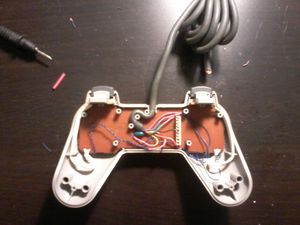
| − | + | First of all, disassemble the PSX controller by removing the screws at the back. Is not complicated to open the case, you won't find any clip or anything. After that, remove the board and front switches that are attached to the board. It would be great if you spend a couple of minutes cleaning the case with some water and soap and leave it drying. | |
| − | + | [[File:Psx controller opened.jpg|300px|Opened PSX controller]] | |
| − | + | === Useless electronics for Amstrad === | |
| − | + | Now, let's have a look to the board. You will see a lot of electronics that we don't need to turn it into an Amstrad controller. Amstrad controllers are digital, but very simple, and they don't need any special electronics to work. We can't get rid of those electronics because they are solded and very tiny, so, we have to disconnect them from the switches on the board. The easiest way to do that is to use a cutter and cut the tracks on the board. After that, all the electronics will be dead and we won't have any short in the future, while operating the controller. | |
| − | + | [[File:Psx controller board 01.jpg|300px|PSX controller board]] | |
| − | |||
| + | Then, if you look inside the main cable at the back of the board, you will see 7 wires coming from the PSX connector in a thick grey cable. Cut 6 out of 7, just leave the black one connected to the board. The black one is ground, and we will keep it as ground for our new Amstrad controller. | ||
| − | |||
| − | [[File:Psx controller | + | [[File:Psx controller cut cables.jpg|300px|Wires from the connector to the board]] |
| − | + | === Rewiring switches === | |
| + | Now you can start soldering the little cables to the switches. Just in case you don't know, switches usually have two contacts. One of them is the common one, ground. The second one is the +5 VDC signal that we will have there when pushed. You should sold six cables, one at each switch that we need, but on the +5 VDC side, not on the ground side. We need six switches and six cables: UP, DOWN, LEFT, RIGHT, FIRE 1 and FIRE 2. Test ground continuity between black ground cable, direction switches and fire switches, by following the circuits on the board. Is not difficult to find the ground common track. You may know some electrics... but is not strictly necessary if you think twice how it works! If you cutted properly all the tracks, you may need an extra wire from main ground black cable to the ground side of the switches on the fire buttons side. | ||
| − | |||
| − | [[File:Psx controller | + | [[File:Psx controller sold cables.jpg|300px|Solded cables]] |
| − | + | ||
| − | + | === Sticking the wires to the board === | |
| − | + | After soldering all the wires, put some Superglue on the wires to keep them at the right position and avoid problems while playing. You just need a drop on each wire and one minute later they will stay there for ages. | |
| + | |||
| + | === Matching wires === | ||
| + | |||
| + | Then, sold the little wires from the board with the wires that come from the PSX plug. Don't forguet to put some sleeve there to avoid shorts and make a good job. Below is displayed the color code that I used to match the wires: | ||
| + | |||
| + | |||
| + | [[File:Psx controller cut tracks.jpg|300px|Cut tracks on the board]] [[File:Psx controller sleeve.jpg|300px|Important: sleeve on wires]] | ||
| + | [[File:Psx amstrad color code.jpg|192px|PSX - Amstrad color code]] | ||
| + | |||
| + | |||
| + | === Final stage === | ||
| + | |||
| + | Put the board back into the case and close it with the screws. Now cut the PSX orginal connector and sold our female DB9 connector, following the same color code and you won't have any problem. | ||
| + | |||
| + | |||
| + | [[File:Psx controller in again.jpg|300px|Closing the controller case]] [[File:Psx controller db9.jpg|300px|Closing DB9 female connector]] | ||
| + | |||
| + | |||
| + | == Beat them all! == | ||
Test, and enjoy your new Amstrad CPC controller!! | Test, and enjoy your new Amstrad CPC controller!! | ||
| − | [[File:Psx controller amstrad finished.jpg|300px]] | + | |
| + | [[File:Psx controller amstrad finished.jpg|300px|Amstrad CPC controller]] | ||
Revision as of 16:42, 24 March 2014
Contents
Description
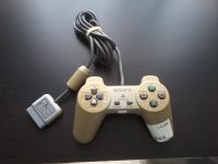
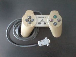
Modify a PSX digital controller to work on Amstrad CPC. The thing is that is very cheap and easy to find a PSX controller on a second hand shop. I just paid €2.50 for this one!!!
Materials you need
- PSX digital controller
- DB9 female connector
- A bunch of little wires
- Small phillips screwdriver
- Cutter or razor
- Some sleeve
- Solder and tin
- Loctite Superglue
- Multimeter to test continuity
How to
Open the case
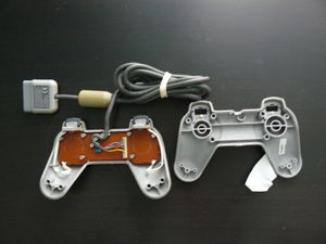
First of all, disassemble the PSX controller by removing the screws at the back. Is not complicated to open the case, you won't find any clip or anything. After that, remove the board and front switches that are attached to the board. It would be great if you spend a couple of minutes cleaning the case with some water and soap and leave it drying.
Useless electronics for Amstrad
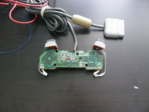
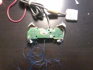
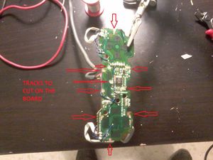
Now, let's have a look to the board. You will see a lot of electronics that we don't need to turn it into an Amstrad controller. Amstrad controllers are digital, but very simple, and they don't need any special electronics to work. We can't get rid of those electronics because they are solded and very tiny, so, we have to disconnect them from the switches on the board. The easiest way to do that is to use a cutter and cut the tracks on the board. After that, all the electronics will be dead and we won't have any short in the future, while operating the controller.
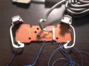
Then, if you look inside the main cable at the back of the board, you will see 7 wires coming from the PSX connector in a thick grey cable. Cut 6 out of 7, just leave the black one connected to the board. The black one is ground, and we will keep it as ground for our new Amstrad controller.
Rewiring switches
Now you can start soldering the little cables to the switches. Just in case you don't know, switches usually have two contacts. One of them is the common one, ground. The second one is the +5 VDC signal that we will have there when pushed. You should sold six cables, one at each switch that we need, but on the +5 VDC side, not on the ground side. We need six switches and six cables: UP, DOWN, LEFT, RIGHT, FIRE 1 and FIRE 2. Test ground continuity between black ground cable, direction switches and fire switches, by following the circuits on the board. Is not difficult to find the ground common track. You may know some electrics... but is not strictly necessary if you think twice how it works! If you cutted properly all the tracks, you may need an extra wire from main ground black cable to the ground side of the switches on the fire buttons side.
Sticking the wires to the board
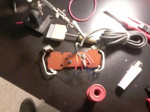
After soldering all the wires, put some Superglue on the wires to keep them at the right position and avoid problems while playing. You just need a drop on each wire and one minute later they will stay there for ages.
Matching wires
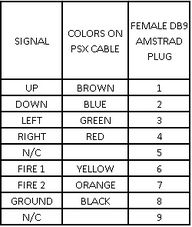
Then, sold the little wires from the board with the wires that come from the PSX plug. Don't forguet to put some sleeve there to avoid shorts and make a good job. Below is displayed the color code that I used to match the wires:
Final stage
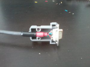
Put the board back into the case and close it with the screws. Now cut the PSX orginal connector and sold our female DB9 connector, following the same color code and you won't have any problem.
Beat them all!
Test, and enjoy your new Amstrad CPC controller!!
Here is a video I made to show you the controller working on my Amstrad. Hope you like it!
Modified PSX controller to work on Amstrad CPC
Guide by Forcy
