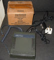
(→Pictures: Added Amstrad_MP1_French_SCART_connectors.jpg) |
NigeNigeNige (Talk | contribs) m (→Manual: Link to user manuals page) |
||
| (7 intermediate revisions by 5 users not shown) | |||
| Line 7: | Line 7: | ||
They provided the power needed by the CPCs, so that you didn't have to carry the monitor around just to have power, and a TV-modulator which modulated the monitor signal in a way that it could be seen on a regular TV-set. | They provided the power needed by the CPCs, so that you didn't have to carry the monitor around just to have power, and a TV-modulator which modulated the monitor signal in a way that it could be seen on a regular TV-set. | ||
| − | Having an MP-1/MP-2 today is more or less just a gimmick, as a self-made [[TV SCART cable]] gives better picture quality (SCART connectors weren't common back in the 80s) and the power can be taken from a PC AT or even ATX power supply as well. | + | Having an MP-1/MP-2 today is more or less just a gimmick, as a self-made [[TV SCART cable]] gives better picture quality (SCART connectors weren't common back in the 80s) and the power can be taken from a PC AT or even ATX power supply as well. To get a slightly better picture, it's also possible to mod the [[LCD And Plasma TV Solution|MP1/2 to output Composite video]]. |
The difference between the MP-1 and MP-2 models is just the additional 12V power supply for the CPC664/CPC6128's disk drive in the later model. | The difference between the MP-1 and MP-2 models is just the additional 12V power supply for the CPC664/CPC6128's disk drive in the later model. | ||
| Line 15: | Line 15: | ||
* Supply In: ~220V/50Hz, 12W | * Supply In: ~220V/50Hz, 12W | ||
* Supply Out: +5V (both MP1 and MP2), +12V (MP2 only) | * Supply Out: +5V (both MP1 and MP2), +12V (MP2 only) | ||
| − | * Video In: RGB, Sync ( | + | * Video In: RGB, Sync (6 pin DIN) |
| − | * Video Out: | + | * Video Out: UHF 36 (591,25 MHz) (2 pin) |
Note: There has been also french versions with Scart RGB output, of the MP1 (no 12V) and MP2 (with 12V), see [[MP2F]]. As well as a spanish version, the [[Amstrad MPV 001 modulator|MPV 001]] (with '''unknown''' output). | Note: There has been also french versions with Scart RGB output, of the MP1 (no 12V) and MP2 (with 12V), see [[MP2F]]. As well as a spanish version, the [[Amstrad MPV 001 modulator|MPV 001]] (with '''unknown''' output). | ||
| Line 22: | Line 22: | ||
== Pictures == | == Pictures == | ||
| − | <gallery caption="MP1"> | + | <gallery caption="Amstrad MP1"> |
Image:Amstrad mp-1.jpg| | Image:Amstrad mp-1.jpg| | ||
</gallery> | </gallery> | ||
| − | <gallery caption="MP1 French version with SCART connector"> | + | <gallery caption="Amstrad MP1 (French version with SCART connector)"> |
Image:Amstrad_MP1_French_SCART.jpg| | Image:Amstrad_MP1_French_SCART.jpg| | ||
Image:Amstrad_MP1_French_SCART_connectors.jpg| | Image:Amstrad_MP1_French_SCART_connectors.jpg| | ||
| + | Image:Amstrad_MP1_French_SCART_inside.jpg| | ||
| + | Image:Amstrad_MP1_French_SCART_inside_rgb_passthrough.jpg| | ||
</gallery> | </gallery> | ||
| − | <gallery caption="MP2"> | + | <gallery caption="Amstrad MP2"> |
Image:mp2 1.JPG| | Image:mp2 1.JPG| | ||
Image:mp2 2.JPG| | Image:mp2 2.JPG| | ||
| Line 37: | Line 39: | ||
Image:mp2 4.JPG| | Image:mp2 4.JPG| | ||
Image:Amstrad mp-2.jpg| | Image:Amstrad mp-2.jpg| | ||
| + | </gallery> | ||
| + | |||
| + | <gallery caption="Schneider MP2"> | ||
| + | Image:Schneider_mp_2_top.png| | ||
| + | Image:Schneider_mp_2_inside.png| | ||
| + | </gallery> | ||
| + | |||
| + | <gallery caption="Amstrad MP-2F"> | ||
| + | Image:MP-2F.jpg| | ||
</gallery> | </gallery> | ||
| Line 43: | Line 54: | ||
== Manual == | == Manual == | ||
| − | The procedure of setting up the CPC with the MP-1/MP-2 modulators is described in the CPC's user manual. | + | The procedure of setting up the CPC with the MP-1/MP-2 modulators is described in the CPC's [[User Manual|user manual]]. |
[[Category:Peripherals]][[Category:CPC Internal Components]][[Category:Amstrad Products]][[Category:Graphic]] | [[Category:Peripherals]][[Category:CPC Internal Components]][[Category:Amstrad Products]][[Category:Graphic]] | ||
Latest revision as of 08:43, 13 February 2023
A TV-modulator and power supply by Amstrad for the classic CPC-computers
As the Amstrad CPCs always came together with a monitor, normally there was no need for a TV modulator inside the CPC as seen on other home computers (Sinclair Spectrum, Commodore C64/C128 and so on). As the power supply was included inside the monitor, there wasn't an external power supply either.
If you bought an Amstrad CPC together with one of the Amstrad GT64/GT65 Green Monitors however, you might have wanted the ability to play games on the colour TV-set later, so Amstrad also made the MP-1/MP-2 devices. They provided the power needed by the CPCs, so that you didn't have to carry the monitor around just to have power, and a TV-modulator which modulated the monitor signal in a way that it could be seen on a regular TV-set.
Having an MP-1/MP-2 today is more or less just a gimmick, as a self-made TV SCART cable gives better picture quality (SCART connectors weren't common back in the 80s) and the power can be taken from a PC AT or even ATX power supply as well. To get a slightly better picture, it's also possible to mod the MP1/2 to output Composite video.
The difference between the MP-1 and MP-2 models is just the additional 12V power supply for the CPC664/CPC6128's disk drive in the later model.
Technical Specs.
- Supply In: ~220V/50Hz, 12W
- Supply Out: +5V (both MP1 and MP2), +12V (MP2 only)
- Video In: RGB, Sync (6 pin DIN)
- Video Out: UHF 36 (591,25 MHz) (2 pin)
Note: There has been also french versions with Scart RGB output, of the MP1 (no 12V) and MP2 (with 12V), see MP2F. As well as a spanish version, the MPV 001 (with unknown output).
Pictures
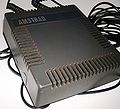
- Amstrad MP1
- Amstrad MP1 (French version with SCART connector)
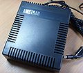
- Amstrad MP2
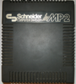
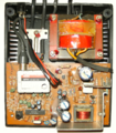
- Schneider MP2
- Amstrad MP-2F
Weblinks
Manual
The procedure of setting up the CPC with the MP-1/MP-2 modulators is described in the CPC's user manual.


