(→Manual) |
m (typo) |
||
| (6 intermediate revisions by 6 users not shown) | |||
| Line 5: | Line 5: | ||
The '''Amstrad Expansion System''' aka '''Maplin ROM Card''' from [[Maplin]] is a DIY project by [[Dave Goodman]] and [[John Attfield]]. | The '''Amstrad Expansion System''' aka '''Maplin ROM Card''' from [[Maplin]] is a DIY project by [[Dave Goodman]] and [[John Attfield]]. | ||
| − | The Amstrad Expansion System (Part 1) | + | The '''Amstrad Expansion System (Part 1)''' is primarily a '''rom box''' for the CPC series, but had additional features: |
| − | * Special non-standard Buffered Expansion Port (with pre-decoded IOSEL line, on access to "free" I/O | + | * Special non-standard Buffered Expansion Port (with pre-decoded IOSEL line, on access to "free" I/O address) |
* Lightpen socket (3.5mm stereo socket - just a connector with LPEN,5V,GND - without any additional electronics) | * Lightpen socket (3.5mm stereo socket - just a connector with LPEN,5V,GND - without any additional electronics) | ||
| − | The | + | The '''Amstrad Expansion System (Part 2)''' adds some more features: |
| + | |||
| + | * 6x8bit I/O port (using two [[8255 PPI chip]]s) | ||
| + | * Additional power-supply module (PSU) | ||
| + | |||
| + | == Technical == | ||
| + | |||
| + | ROM is selected using an I/O port decoded with A15=1, A13=0. The ROM number is decoded using D3-D0 only, meaning a maximum of 16 ROMs can be used, but the PCB only has 8 sockets available. | ||
| + | In addition more then one value can select the same ROM. | ||
== Pictures == | == Pictures == | ||
| Line 19: | Line 27: | ||
Image:ROMBOX_04_MANUAL.JPG|ROM Box and photocopy of how-to build manual | Image:ROMBOX_04_MANUAL.JPG|ROM Box and photocopy of how-to build manual | ||
Image:ROMBOX_05_SCREEN.JPG|Connected showing ROMs | Image:ROMBOX_05_SCREEN.JPG|Connected showing ROMs | ||
| + | Image:Maplin_ROMBoard_PCB_Top_(1).jpg|PCB Top (1) | ||
| + | Image:Maplin_ROMBoard_PCB_Bottom_(1).jpg|PCB Bottom (1) | ||
| + | Image:Maplin_ROMBoard_PCB_Top_(2).jpg|PCB Top (2) | ||
| + | Image:Maplin_ROMBoard_PCB_Bottom_(2).jpg|PCB Bottom (2) | ||
</gallery> | </gallery> | ||
| Line 25: | Line 37: | ||
* [[Media:Maplin ROM-Box Manual.pdf|Amstrad Expansion System Part 1: Maplin ROM-Box Manual]] (pdf) | * [[Media:Maplin ROM-Box Manual.pdf|Amstrad Expansion System Part 1: Maplin ROM-Box Manual]] (pdf) | ||
* [[Media:Maplins Amstrad Expansion System Part 2 (Project Book19).pdf|Amstrad Expansion System Part 2: 6x8bit I/O Port]] (pdf) | * [[Media:Maplins Amstrad Expansion System Part 2 (Project Book19).pdf|Amstrad Expansion System Part 2: 6x8bit I/O Port]] (pdf) | ||
| + | |||
| + | == Additional == | ||
| + | |||
| + | * [[Media:Maplin Video Digitiser.pdf| Maplin Video Digitiser DIY Kit Article]] (pdf) | ||
| + | "Electronics - The Maplin Magazine" Dec 1985-Nov 1986. Published by Maplin Electronic Supplies Ltd. Page 12 - 18; Video Digitiser. This DIY Kit could be assembled for use in the Buffered Eurocard Extension board of the Maplin ROM Box for use with Amstrad CPC and Z80 Computers. Gives full instructions on how to build it with board layout and list of components. | ||
== Weblinks == | == Weblinks == | ||
* [http://en.wikipedia.org/wiki/Eurocard Info on EURO-card standard] | * [http://en.wikipedia.org/wiki/Eurocard Info on EURO-card standard] | ||
| − | * http://www.maplin.co.uk | + | * http://www.maplin.co.uk |
| − | [[Category: | + | [[Category:Expansion ROM]] [[Category:Peripherals]] [[Category:manual]] |
Latest revision as of 21:32, 23 July 2016

Description
The Amstrad Expansion System aka Maplin ROM Card from Maplin is a DIY project by Dave Goodman and John Attfield.
The Amstrad Expansion System (Part 1) is primarily a rom box for the CPC series, but had additional features:
- Special non-standard Buffered Expansion Port (with pre-decoded IOSEL line, on access to "free" I/O address)
- Lightpen socket (3.5mm stereo socket - just a connector with LPEN,5V,GND - without any additional electronics)
The Amstrad Expansion System (Part 2) adds some more features:
- 6x8bit I/O port (using two 8255 PPI chips)
- Additional power-supply module (PSU)
Technical
ROM is selected using an I/O port decoded with A15=1, A13=0. The ROM number is decoded using D3-D0 only, meaning a maximum of 16 ROMs can be used, but the PCB only has 8 sockets available. In addition more then one value can select the same ROM.
Pictures
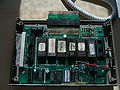
ROM Box with ROMs
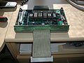
ROM Box
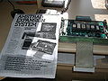
ROM Box and photocopy of how-to build manual
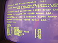
Connected showing ROMs
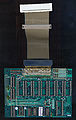
PCB Top (1)
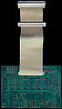
PCB Bottom (1)
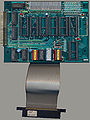
PCB Top (2)
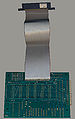
PCB Bottom (2)


.jpg)
.jpg)
.jpg)
.jpg)
Manual
Additional
"Electronics - The Maplin Magazine" Dec 1985-Nov 1986. Published by Maplin Electronic Supplies Ltd. Page 12 - 18; Video Digitiser. This DIY Kit could be assembled for use in the Buffered Eurocard Extension board of the Maplin ROM Box for use with Amstrad CPC and Z80 Computers. Gives full instructions on how to build it with board layout and list of components.