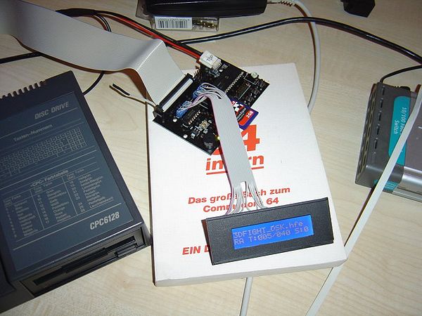
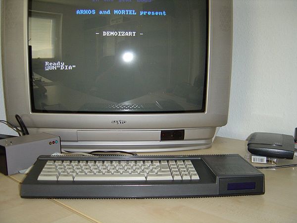
(Created page with '== Description == The following steps show how to install the HxC SDCard Drive as an internal drive on a CPC6128 == What You Need == * An old faulty 3"inch disc drive * A Doub…') |
|||
| (17 intermediate revisions by 3 users not shown) | |||
| Line 1: | Line 1: | ||
| + | *[[HxC Floppy Emulator]] | ||
| + | *[[HxC Standalone Floppy Emulator]] | ||
| + | *[[HxC SDCard Internal]] | ||
| + | *[[Guide for HxC USB Version]] | ||
| + | *[[Guide for HxC SD Version]] | ||
| + | |||
| + | |||
== Description == | == Description == | ||
| − | The following steps show how to install the HxC | + | The following steps show how to install the [[HxC Floppy Emulator]] as an internal drive on a CPC6128 |
| + | |||
| + | You may also want to see the [[Guide for HxC USB Version]] | ||
== What You Need == | == What You Need == | ||
| + | |||
* An old faulty 3"inch disc drive | * An old faulty 3"inch disc drive | ||
* A Double Contacted Perfboard (160x100) | * A Double Contacted Perfboard (160x100) | ||
* A Soldering Iron / Solder | * A Soldering Iron / Solder | ||
| + | * A Hot-glue Pistol | ||
* A Vacuum Pump for Desoldering (if you make a mistake) | * A Vacuum Pump for Desoldering (if you make a mistake) | ||
* Some 40way Ribbon Cable | * Some 40way Ribbon Cable | ||
| Line 14: | Line 25: | ||
* A Sharp Knife | * A Sharp Knife | ||
* A Modellers Drill for cutting, drilling | * A Modellers Drill for cutting, drilling | ||
| − | * A DVD | + | * A DVD Case (preferrably black) |
* 3 Micro Switch Buttons | * 3 Micro Switch Buttons | ||
* 2 Self-adhiesive Plastic Motherboard Distance Rods | * 2 Self-adhiesive Plastic Motherboard Distance Rods | ||
| Line 21: | Line 32: | ||
== Dismantling The Drive == | == Dismantling The Drive == | ||
| + | |||
First we dismantle the original faulty Amstrad 3" inch Disc Drive. You will be amazed how many parts are inside this old thingy. | First we dismantle the original faulty Amstrad 3" inch Disc Drive. You will be amazed how many parts are inside this old thingy. | ||
| Line 33: | Line 45: | ||
[[Image:SDTut2.JPG|600px|centre]] | [[Image:SDTut2.JPG|600px|centre]] | ||
| − | [[ | + | |
| + | Now cut a perfboard to fit inside the frame. I used the Drill for that, but you can use a sharp scissors or a saw too. | ||
| + | |||
| + | |||
| + | [[Image:SDTut3.JPG|600px|centre]] | ||
| + | |||
| + | |||
| + | [[Image:SDTut4.JPG|600px|centre]] | ||
| + | |||
| + | |||
| + | Looks nice eh? Well done, but still lots to do now.... | ||
| + | |||
| + | |||
| + | Now you look under the frame and drill some holes into the old mounting holes from the Disc Drive PCB. You can use the old screws and drill them inside the new perfboard. On the top you use some Tape Strips to isolate the metal screws. It should look like this: | ||
| + | |||
| + | |||
| + | |||
| + | [[Image:SDTut5.JPG|600px|centre]] | ||
| + | |||
| + | |||
| + | I used the old screws from the amstrad disc drive to hold the new perfboard. | ||
| + | |||
| + | |||
| + | [[Image:SDTut6.JPG|600px|centre]] | ||
| + | |||
| + | |||
| + | Next we do a new frontplate for your old Disc Drive from an DVD Case. Open the Case and cut out a piece of plastic with a sharp knife. | ||
| + | Its easy to do, as you can see from the pictures. | ||
| + | |||
| + | |||
| + | |||
| + | [[Image:SDTut7.JPG|600px|centre]] | ||
| + | |||
| + | |||
| + | [[Image:SDTut8.JPG|600px|centre]] | ||
| + | |||
| + | |||
| + | Fits nice doesn't it? What a good idea of mine ? LOL :-) go on, you still have a lot to do... | ||
| + | |||
| + | |||
| + | Next step is to cut out the Frontplate of the Amstrad Disc Drive. So we can snap in the Display of the SDCard HxC. Remove the Display from your HxC now and use a caliper to measure out the frame and the Display. Then cut out the frame with the drill. It stinks and make lots of noises, but hey we love that don't we? Be careful with the old plastic. Its a thermoplast and you dont need much power to cut that out. It's easy to do. After cutting, use a file to smooth the edges. If you have done it correctly, the Display snaps into old Amstrad Frontplate. | ||
| + | |||
| + | |||
| + | [[Image:SDTut9.JPG|600px|centre]] | ||
| + | |||
| + | |||
| + | [[Image:SDTut10.JPG|600px|centre]] | ||
| + | |||
| + | |||
| + | Now open your holy CPC6128 by removing the upper case. Please be careful with the Keyboards foil. Open from right to left side. You can see the foil connection here: | ||
| + | |||
| + | |||
| + | [[Image:SDTut11.JPG|600px|centre]] | ||
| + | |||
| + | |||
| + | I'm sure you all know whats inside a CPC 6128 looks like. But if you really open it for the first time in your life, then dont be panic. You cant destroy anything here unless you are really stupid or clumsy. | ||
| + | |||
| + | Remove the internal 3inch Disc Drive now. You need a screwdriver to open the two screws on the left of the frame. Pull up the connectors and that's it. | ||
| + | Now we can put in our new almost finished SDCard HxC Drive for a first look. | ||
| + | |||
| + | |||
| + | [[Image:SDTut12.JPG|600px|centre]] | ||
| + | |||
| + | |||
| + | Wow .... yes you did it and it's looking nice. But there's still a lot to do. So lets continue with soldering a simple LCD Cable to connect the HxC LCD Display with the board. | ||
| + | |||
| + | Its easy to do. I used some really simple parts and PC Jumpers for connection. I had 1000s of them in my room and so I decided to use them for this purpose. You can buy a real connector if you like a better look. I am a nerd so i am using jumpers. LOL | ||
| + | |||
| + | |||
| + | [[Image:SDTut13.JPG|600px|centre]] | ||
| + | |||
| + | |||
| + | Well done, you did your first soldering for today and a good job if your LCD is still working correctly. So on to the next steps..... | ||
| + | |||
| + | Change the red and the orange wire of the Disc Drive power connector inside your CPC6128 and remove the 12V spiral cable. You won't ever need it again. The CPC doesn't use the standard pinout, 12V and 5v are not connected in normal way. So we change it back to the standard pinout. 5Volt at the correct side please. I used a micro screwdriver to hold up the little white pin and pull out the cable. Then simply change its position. It clicks smoothly inside....done..... | ||
| + | |||
| + | |||
| + | [[Image:SDTut14.JPG|600px|centre]] | ||
| + | |||
| + | |||
| + | Now you drill a large hole at the left side of your new perfboard pcb and file it clean and smooth like I did here: | ||
| + | |||
| + | |||
| + | [[Image:SDTut15.JPG|600px|centre]] | ||
| + | |||
| + | |||
| + | Then I crimped a CPC6128 internal 3,5" Disc Drive adapter cable. You can find the instructions to do that on the spanish CPC sites or use this picture. It speaks for itself and you can crimp it like its done here. I used the same picture and its working fine. Dont solder a Side Select Switch. The HxC doesn't need a side switch. I kept the bridge open and NOT soldered together. The other bridges are soldered together like in the picture: | ||
| + | |||
| + | |||
| + | [[Image:SDTut16.JPG|600px|centre]] | ||
| + | |||
| + | |||
| + | I cut the wires so that it's more flexible and fits easier through the newly drilled hole of your perfboard PCB. I used some tape strips to fix the cable and the connector to the perfboard. | ||
| + | |||
| + | |||
| + | [[Image:SDTut17.JPG|600px|centre]] | ||
| + | |||
| + | |||
| + | [[Image:SDTut18.JPG|600px|centre]] | ||
| + | |||
| + | |||
| + | [[Image:SDTut19.JPG|600px|centre]] | ||
| + | |||
| + | |||
| + | Now you need a hot-glue pistol to glue the connector to your perfboard PCB. | ||
| + | |||
| + | |||
| + | [[Image:SDTut20.JPG|600px|centre]] | ||
| + | |||
| + | |||
| + | Now you can mount the metal bracket back to the frame, install the LCD and fix it with a small strip of tape or some hot-glue. | ||
| + | |||
| + | |||
| + | [[Image:SDTut21.JPG|600px|centre]] | ||
| + | |||
| + | |||
| + | [[Image:SDTut22.JPG|600px|centre]] | ||
| + | |||
| + | |||
| + | As you can see I made a nice cable harness and it's flexible enough not to damage the HxC PCB or the LCD. | ||
| + | |||
| + | |||
| + | The next steps should be done very slowly and carefully, with lots of patience and please do an exact measurement for cutting out the slot and the micro switches. The Slot is 3cm above the table surface and its a bit tricky to do that, but I know you can do it. Patience is most important and you will get a good result. | ||
| + | |||
| + | Lets see, drill, cut and file now: | ||
| + | |||
| + | |||
| + | [[Image:SDTut23.JPG|600px|centre]] | ||
| + | |||
| + | |||
| + | A bit rough no? Not looking nice..... I can do that better ! | ||
| + | |||
| + | |||
| + | [[Image:SDTut24.JPG|600px|centre]] | ||
| + | |||
| + | |||
| + | Connect your new 3inch HxC now to your CPC and do a full function test. If its working fine, we can continue with some more great case modding. | ||
| + | |||
| + | The next step is to drill the 3 holes for the microswitches. I am using the same switches like Lotharek did but larger diameter of 8mm. I soldered 3 microswitches at a perfboard pcb in a row. The space between them is about 0.75 cm but please measure this yourself to be sure. I used the middle and did it like this: | ||
| + | |||
| + | |||
| + | [[Image:SDTut25.JPG|600px|centre]] | ||
| + | |||
| + | |||
| + | [[Image:SDTut26.JPG|600px|centre]] | ||
| + | |||
| + | |||
| + | Yes yes, I know there is a scratch on my case. Its been there for 20 years so I am okay with that. LOL it's not an accident during case mod. It was my brother a long time ago with his old digital watch...... fairy tales.... lets go back to work now. | ||
| + | |||
| + | You can see I am using self adhesive PCB distance rods to mount the microswitch pcb. It's so simple to do, if you drilled the holes correctly you just need to press it inside and voila its done. Like this: | ||
| + | |||
| + | |||
| + | [[Image:SDTut27.JPG|600px|centre]] | ||
| + | |||
| + | Do you see how smooth the SD Card fits in your new case mod? WOW, and there is still enough space for your sausagefingers to pull it out again. Its working fine and looks perfect. | ||
| + | |||
| + | |||
| + | [[Image:SDTut28.JPG|600px|centre]] | ||
| + | |||
| + | |||
| + | NOW YOU ARE DONE.... Congratulations you did a great job. Let's do an intensive function test with loading a Demo or some games. If everything is working fine, you can screw the case back together again and you are done. I did some more mods and changed the Power LED from RED to a pink ones now, but that's just for fun. | ||
| + | |||
| + | |||
| + | [[Image:SDTut29.JPG|600px|centre]] | ||
| + | |||
| + | |||
| + | |||
| + | == Still to do if you like == | ||
| + | |||
| + | |||
| + | Desolder the SMD LED from HxC PCB and add some nice LEDs to the CPC Case. I haven't done this, because its so complicated to do this with an SMD soldering iron - maybe I will do it in future. | ||
| + | |||
| + | Changing the Original ROM to a 2010 Version with new Entry screen and colours - I will do that next week because I need a new programmer to do that. Story will continue... | ||
| + | |||
| + | There is still a lot of space inside your CPC6128 now. You can add a harddisc or a memory expansion under the new 3inch SD Card HxC Drive. I will check out if its possible to add a 3,5inch B: Drive internal. Maybe i will try that with a slimline Disc Drive. The result is that you have a complete all in one CPC6128 and no external periphery at your desk. Well we will see...... | ||
| + | |||
| + | |||
| + | Tutorial by: | ||
| + | |||
| + | Tom / Pentagon of Noob Inc. 2010 | ||
| + | |||
| + | Originally posted in the WikiForum : [http://cpcwiki.eu/forum/index.php/topic,1106.0.html How to build an internal 3 inch SDCard HxC drive for your Amstrad ] - More photos and commentary can be found here also. | ||
| + | |||
| + | [[Category:Peripherals]] [[Category:DIY]][[Category:DATA Storage]][[Category:Picture Gallery]] | ||
Latest revision as of 15:43, 19 December 2010
- HxC Floppy Emulator
- HxC Standalone Floppy Emulator
- HxC SDCard Internal
- Guide for HxC USB Version
- Guide for HxC SD Version
Description
The following steps show how to install the HxC Floppy Emulator as an internal drive on a CPC6128
You may also want to see the Guide for HxC USB Version
What You Need
- An old faulty 3"inch disc drive
- A Double Contacted Perfboard (160x100)
- A Soldering Iron / Solder
- A Hot-glue Pistol
- A Vacuum Pump for Desoldering (if you make a mistake)
- Some 40way Ribbon Cable
- A 26 Pin Socket Connector
- A 40 Pin Socket Connector
- A Sharp Knife
- A Modellers Drill for cutting, drilling
- A DVD Case (preferrably black)
- 3 Micro Switch Buttons
- 2 Self-adhiesive Plastic Motherboard Distance Rods
- Lots Of Old PC Motherboard Jumpers
- Patience And A Big Cup Of Coffee
Dismantling The Drive
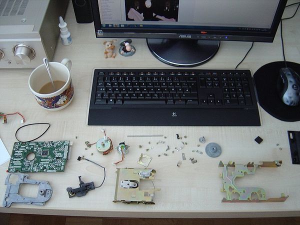
First we dismantle the original faulty Amstrad 3" inch Disc Drive. You will be amazed how many parts are inside this old thingy.
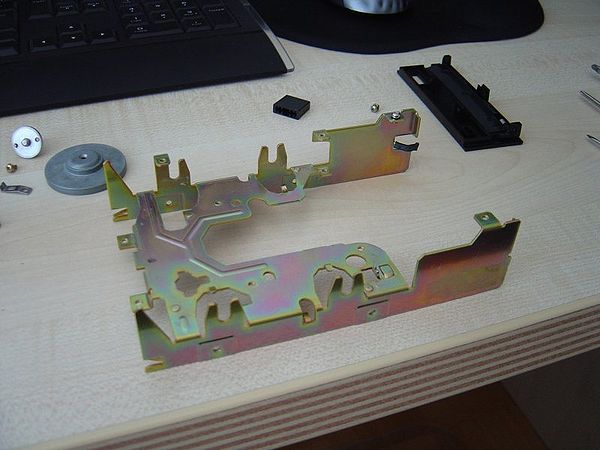
We will just use the frame of the drive:
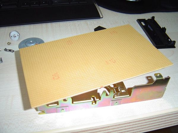
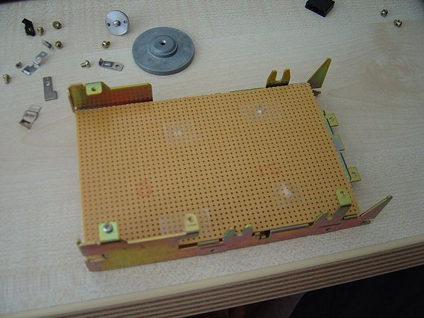
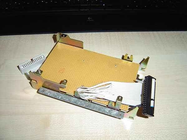
Now cut a perfboard to fit inside the frame. I used the Drill for that, but you can use a sharp scissors or a saw too.
Looks nice eh? Well done, but still lots to do now....
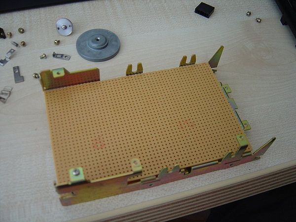
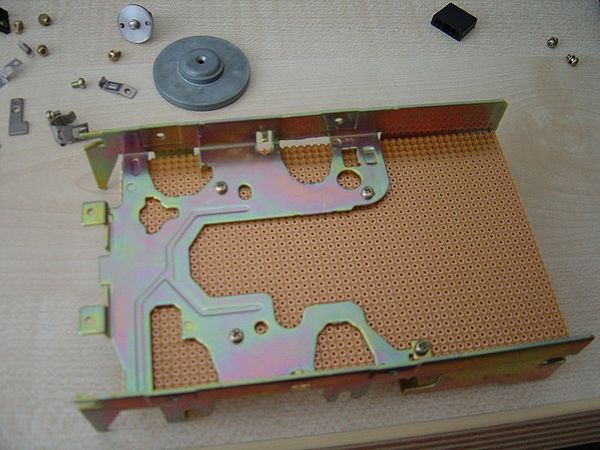
Now you look under the frame and drill some holes into the old mounting holes from the Disc Drive PCB. You can use the old screws and drill them inside the new perfboard. On the top you use some Tape Strips to isolate the metal screws. It should look like this:
I used the old screws from the amstrad disc drive to hold the new perfboard.
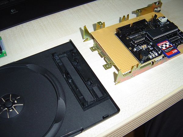
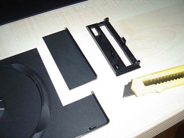
Next we do a new frontplate for your old Disc Drive from an DVD Case. Open the Case and cut out a piece of plastic with a sharp knife.
Its easy to do, as you can see from the pictures.
Fits nice doesn't it? What a good idea of mine ? LOL :-) go on, you still have a lot to do...
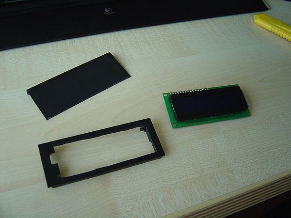
Next step is to cut out the Frontplate of the Amstrad Disc Drive. So we can snap in the Display of the SDCard HxC. Remove the Display from your HxC now and use a caliper to measure out the frame and the Display. Then cut out the frame with the drill. It stinks and make lots of noises, but hey we love that don't we? Be careful with the old plastic. Its a thermoplast and you dont need much power to cut that out. It's easy to do. After cutting, use a file to smooth the edges. If you have done it correctly, the Display snaps into old Amstrad Frontplate.
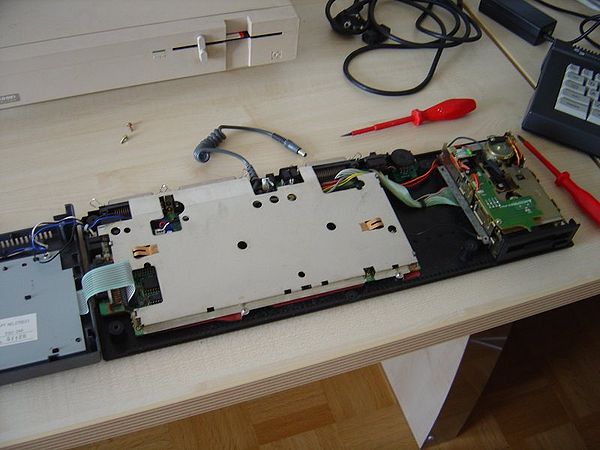
Now open your holy CPC6128 by removing the upper case. Please be careful with the Keyboards foil. Open from right to left side. You can see the foil connection here:
I'm sure you all know whats inside a CPC 6128 looks like. But if you really open it for the first time in your life, then dont be panic. You cant destroy anything here unless you are really stupid or clumsy.
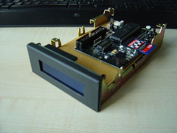
Remove the internal 3inch Disc Drive now. You need a screwdriver to open the two screws on the left of the frame. Pull up the connectors and that's it. Now we can put in our new almost finished SDCard HxC Drive for a first look.
Wow .... yes you did it and it's looking nice. But there's still a lot to do. So lets continue with soldering a simple LCD Cable to connect the HxC LCD Display with the board.
Its easy to do. I used some really simple parts and PC Jumpers for connection. I had 1000s of them in my room and so I decided to use them for this purpose. You can buy a real connector if you like a better look. I am a nerd so i am using jumpers. LOL
Well done, you did your first soldering for today and a good job if your LCD is still working correctly. So on to the next steps.....
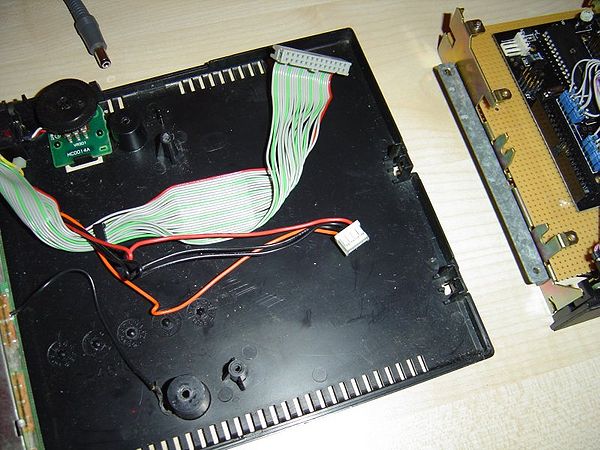
Change the red and the orange wire of the Disc Drive power connector inside your CPC6128 and remove the 12V spiral cable. You won't ever need it again. The CPC doesn't use the standard pinout, 12V and 5v are not connected in normal way. So we change it back to the standard pinout. 5Volt at the correct side please. I used a micro screwdriver to hold up the little white pin and pull out the cable. Then simply change its position. It clicks smoothly inside....done.....
Now you drill a large hole at the left side of your new perfboard pcb and file it clean and smooth like I did here:
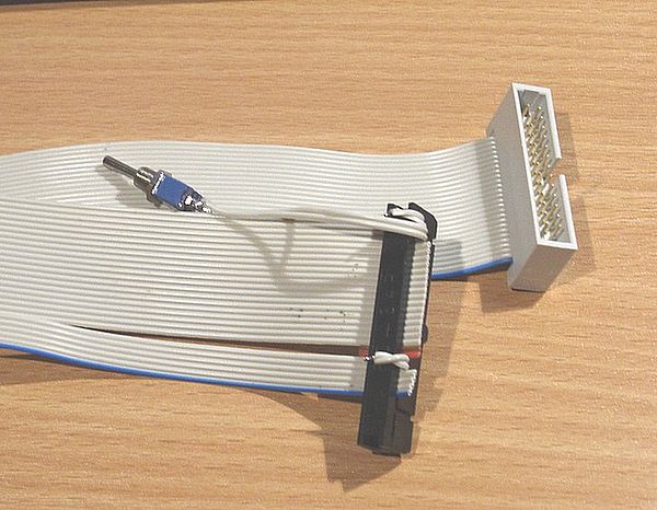
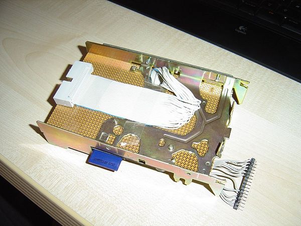
Then I crimped a CPC6128 internal 3,5" Disc Drive adapter cable. You can find the instructions to do that on the spanish CPC sites or use this picture. It speaks for itself and you can crimp it like its done here. I used the same picture and its working fine. Dont solder a Side Select Switch. The HxC doesn't need a side switch. I kept the bridge open and NOT soldered together. The other bridges are soldered together like in the picture:
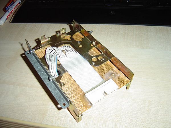
I cut the wires so that it's more flexible and fits easier through the newly drilled hole of your perfboard PCB. I used some tape strips to fix the cable and the connector to the perfboard.
Now you need a hot-glue pistol to glue the connector to your perfboard PCB.
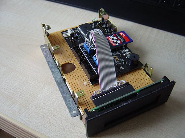
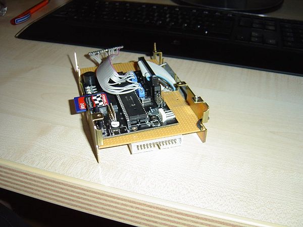
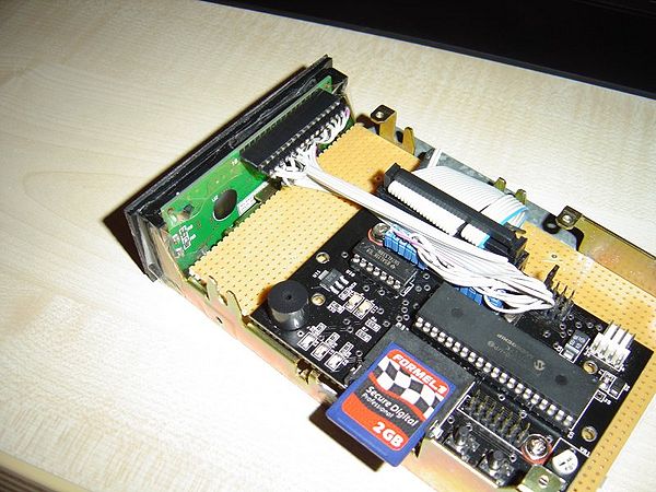
Now you can mount the metal bracket back to the frame, install the LCD and fix it with a small strip of tape or some hot-glue.
As you can see I made a nice cable harness and it's flexible enough not to damage the HxC PCB or the LCD.
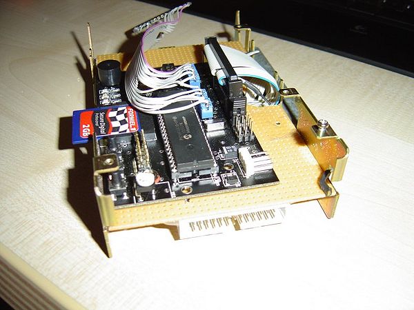
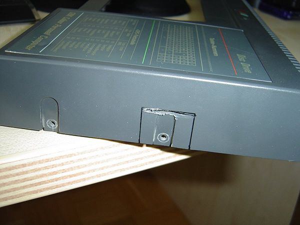
The next steps should be done very slowly and carefully, with lots of patience and please do an exact measurement for cutting out the slot and the micro switches. The Slot is 3cm above the table surface and its a bit tricky to do that, but I know you can do it. Patience is most important and you will get a good result.
Lets see, drill, cut and file now:
A bit rough no? Not looking nice..... I can do that better !
Connect your new 3inch HxC now to your CPC and do a full function test. If its working fine, we can continue with some more great case modding.
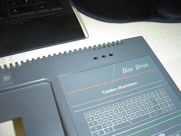
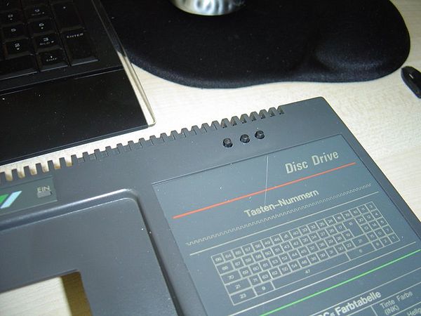
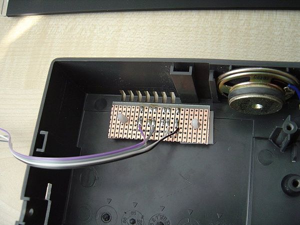
The next step is to drill the 3 holes for the microswitches. I am using the same switches like Lotharek did but larger diameter of 8mm. I soldered 3 microswitches at a perfboard pcb in a row. The space between them is about 0.75 cm but please measure this yourself to be sure. I used the middle and did it like this:
Yes yes, I know there is a scratch on my case. Its been there for 20 years so I am okay with that. LOL it's not an accident during case mod. It was my brother a long time ago with his old digital watch...... fairy tales.... lets go back to work now.
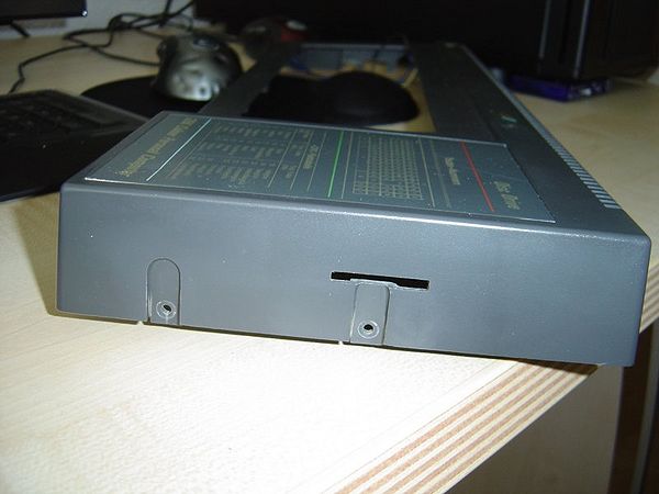
You can see I am using self adhesive PCB distance rods to mount the microswitch pcb. It's so simple to do, if you drilled the holes correctly you just need to press it inside and voila its done. Like this:
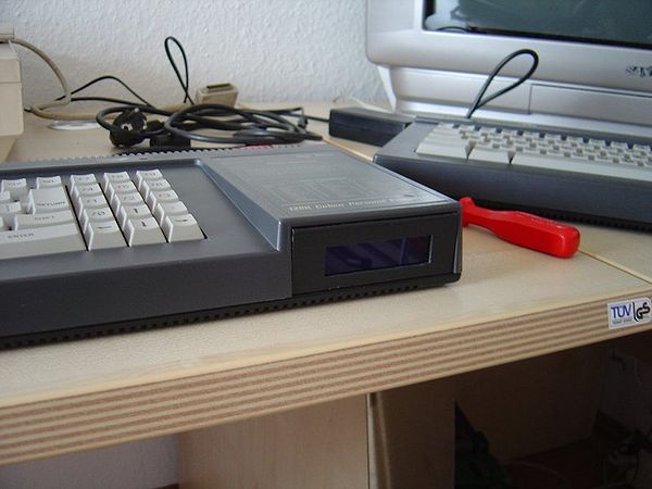
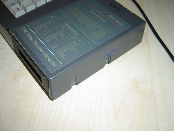
Do you see how smooth the SD Card fits in your new case mod? WOW, and there is still enough space for your sausagefingers to pull it out again. Its working fine and looks perfect.
NOW YOU ARE DONE.... Congratulations you did a great job. Let's do an intensive function test with loading a Demo or some games. If everything is working fine, you can screw the case back together again and you are done. I did some more mods and changed the Power LED from RED to a pink ones now, but that's just for fun.
Still to do if you like
Desolder the SMD LED from HxC PCB and add some nice LEDs to the CPC Case. I haven't done this, because its so complicated to do this with an SMD soldering iron - maybe I will do it in future.
Changing the Original ROM to a 2010 Version with new Entry screen and colours - I will do that next week because I need a new programmer to do that. Story will continue...
There is still a lot of space inside your CPC6128 now. You can add a harddisc or a memory expansion under the new 3inch SD Card HxC Drive. I will check out if its possible to add a 3,5inch B: Drive internal. Maybe i will try that with a slimline Disc Drive. The result is that you have a complete all in one CPC6128 and no external periphery at your desk. Well we will see......
Tutorial by:
Tom / Pentagon of Noob Inc. 2010
Originally posted in the WikiForum : How to build an internal 3 inch SDCard HxC drive for your Amstrad - More photos and commentary can be found here also.
