(→CPC Classic Schematics) |
|||
| (20 intermediate revisions by 5 users not shown) | |||
| Line 2: | Line 2: | ||
<gallery caption="System Schematics"> | <gallery caption="System Schematics"> | ||
| − | File:Schaltplan_cpc_464.jpg|Amstrad CPC464 | + | File:464Schematic_new.png|Amstrad CPC464 (new) |
| − | File:CPC664_Schematic.png|Amstrad CPC664 | + | File:Schaltplan_cpc_464.jpg|Amstrad CPC464 (scan) |
| − | File:CPC6128_Schematic.png|Amstrad CPC6128 | + | File:CPC664_Schematic.png|Amstrad CPC664 (main) |
| + | File:CPC664 Disk Interface Schematic.png|Amstrad CPC664 (disc) | ||
| + | File:CPC6128_Schematic.png|Amstrad CPC6128 (main) | ||
| + | File:CPC6128 Disk Interface Schematic.png|Amstrad CPC6128 (disc) | ||
File:CPC_Disc_Cassette_Schematic.gif|Disc And Cassette Schematics | File:CPC_Disc_Cassette_Schematic.gif|Disc And Cassette Schematics | ||
</gallery> | </gallery> | ||
| + | |||
| + | # Important: There are several versions of the 464 and 6128 motherboards with more or less different schematics. Make sure to check the service manuals for your specific motherboard version if you recognize a difference. | ||
| + | # HighRes scalable version of the CPC464 Schematics: [[Media:464SchematicRedraw_white.pdf|464SchematicRedraw_white.pdf]] | ||
| + | # A full KiCad 6 schematic and pcb layout for the MC0020x CPC6128 boards (featuring the "new" gate array and 24-pin data separator IC) is available at https://github.com/pelrun/cpc-schematics | ||
<gallery caption="Monitor Schematics"> | <gallery caption="Monitor Schematics"> | ||
| Line 21: | Line 28: | ||
== CPC Plus Schematics == | == CPC Plus Schematics == | ||
| − | <gallery caption="Original Scans (high-resolution, with lots of blank space"> | + | <gallery caption="Original Scans (high-resolution, with lots of blank space)"> |
File:CPC_Plus_CPU_Schematic.jpg|CPU Schematic | File:CPC_Plus_CPU_Schematic.jpg|CPU Schematic | ||
File:CPC_Plus_Asic_Schematic.GIF|Asic Schematic | File:CPC_Plus_Asic_Schematic.GIF|Asic Schematic | ||
| Line 49: | Line 56: | ||
File:GX4000_RGB_Schematic.png|RGB Conversion Schematic | File:GX4000_RGB_Schematic.png|RGB Conversion Schematic | ||
File:GX4000_Power_Schematic.png|Power Supply Schematic | File:GX4000_Power_Schematic.png|Power Supply Schematic | ||
| + | </gallery> | ||
| + | |||
| + | <gallery caption="GX4000 - Edited version (lower resolution, less white space)"> | ||
| + | File:Edited GX4000 ASIC Schematic.gif|ASIC Schematic | ||
| + | File:Edited GX4000 Vid Mem Cpu Schematic.gif|CPU Video Memory | ||
| + | File:Edited GX4000 RGB Power Schematic.gif|RGB and Power (PAL) | ||
| + | File:Edited GX4000 French Schematic.gif|RGB and Power (French) | ||
| + | |||
</gallery> | </gallery> | ||
| Line 62: | Line 77: | ||
File:Kcc component map modulator.gif|Component Map (Modulator) | File:Kcc component map modulator.gif|Component Map (Modulator) | ||
</gallery> | </gallery> | ||
| + | |||
| + | == Aleste 520EX Schematics (Russian CPC clone) == | ||
| + | |||
| + | <gallery> | ||
| + | File:Aleste-Schematic1.gif|Schematic 1/4 | ||
| + | File:Aleste-Schematic2.gif|Schematic 2/4 | ||
| + | File:Aleste-Schematic3.gif|Schematic 3/4 | ||
| + | File:Aleste-Schematic4.gif|Schematic 4/4 | ||
| + | File:Aleste-Component-Map.gif|Component Map | ||
| + | </gallery> | ||
| + | |||
| + | For reference, the original '''unedited''' schematics are here: | ||
| + | [[Media:Black-Aleste-Schematic1.gif|Sheet 1]], | ||
| + | [[Media:Black-Aleste-Schematic2.gif|Sheet 2]], | ||
| + | [[Media:Black-Aleste-Schematic3.gif|Sheet 3]], | ||
| + | [[Media:Black-Aleste-Schematic4.gif|Sheet 4]], and | ||
| + | [[Media:Black-Aleste-Component-Map.gif|Component Map]] | ||
== Additional Hardware == | == Additional Hardware == | ||
| Line 71: | Line 103: | ||
* '''Note''' - Further schematics are found in the [[Service Manuals]]. | * '''Note''' - Further schematics are found in the [[Service Manuals]]. | ||
| − | [[Category:Hardware]][[Category:CPC Internal Components]] | + | == Datasheets == |
| + | * [[media:BCD to Decimal Decoders HD74LS145.pdf|Decoder 74LS145 datasheet]] | ||
| + | * [[media:Line to 1-Line Data Selectors-Multiplexers x2 HD74LS153.pdf|MUX 74LS153 datasheet]] | ||
| + | * [[media:Buffers Lines Drivers-Receivers x8 HD74LS244.pdf|Data buffer 74LS244 datasheet]] | ||
| + | * [[media:Gates Flip-Flops x8 HD74LS273.pdf|Printer port latch 74LS273 datasheet]] | ||
| + | * [[media:D-type Transparent Latches x8 HD74LS373.pdf|Data latch/buffer 74LS373 datasheet]] | ||
| + | * [[media:MC74HC4051 datasheet.pdf|8-Analog multiplexer 74HC4051 datasheet]] | ||
| + | |||
| + | [[Category:Hardware| ]][[Category:CPC Internal Components| ]][[Category:Amstrad CPC media]][[Category:Picture Gallery]][[Category:Electronic Component| ]][[Category:Clones|*]][[Category:CPC Plus|*]] | ||
Latest revision as of 06:22, 2 October 2025
CPC Classic Schematics
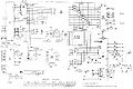
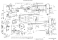
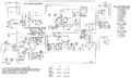
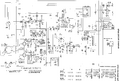
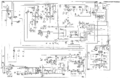
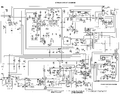
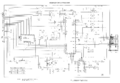
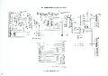
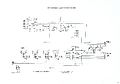
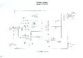
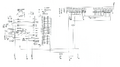
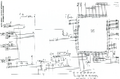
- System Schematics
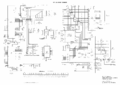
Amstrad CPC464 (new)
Amstrad CPC464 (scan)
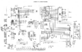
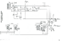
Amstrad CPC664 (main)

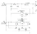
Amstrad CPC664 (disc)
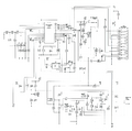
Amstrad CPC6128 (main)
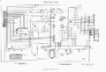
Amstrad CPC6128 (disc)
Disc And Cassette Schematics


- Important: There are several versions of the 464 and 6128 motherboards with more or less different schematics. Make sure to check the service manuals for your specific motherboard version if you recognize a difference.
- HighRes scalable version of the CPC464 Schematics: 464SchematicRedraw_white.pdf
- A full KiCad 6 schematic and pcb layout for the MC0020x CPC6128 boards (featuring the "new" gate array and 24-pin data separator IC) is available at https://github.com/pelrun/cpc-schematics
- Monitor Schematics
GT64
GT65
CTM640
CTM644


- Disk Drive Interface Schematics
DDI

CPC Plus Schematics
- Original Scans (high-resolution, with lots of blank space)
CPU Schematic
Asic Schematic
Video and Memory Schematic
Cassette Schematic


- Edited (lower resolution, less blank space, more concentrated info)
CPU Schematic
Asic Schematic
Video and Memory Schematic
Cassette Schematic


- Monitor Schematics
MM12 Schematic
CM14 Power And Sound Schematic
CM14 Video Schematic


GX4000 Schematics
- System Schematics
CPU Schematic
Asic Schematic
Video and Memory Schematic
RGB Conversion Schematic
Power Supply Schematic


- GX4000 - Edited version (lower resolution, less white space)
ASIC Schematic
CPU Video Memory
RGB and Power (PAL)
RGB and Power (French)


KC Compact Schematics (East German CPC clone)
CPU and I/O Schematic
Memory Schematic
Modulator Schematic
Video and Power Schematic
Block Diagram
Component Map (Mainboard)
Component Map (Modulator)


Aleste 520EX Schematics (Russian CPC clone)
Schematic 1/4
Schematic 2/4
Schematic 3/4
Schematic 4/4
Component Map


For reference, the original unedited schematics are here: Sheet 1, Sheet 2, Sheet 3, Sheet 4, and Component Map
Additional Hardware
- 3 1/2" & 5 1/4" Disk Drives (errr. no schematics here, no pinouts, nothing?)
- Peripherals (contains schematics - as far as any do exist)
- Joystick Y-cables (with schematics)
- TV Scart cable (with schematics)
- Note - Further schematics are found in the Service Manuals.