Difference between revisions of "RGB SVideo"
(→NTSC) |
|||
| Line 18: | Line 18: | ||
[[Image:AD724_Mod_Schematic.PNG|600px|centre]] | [[Image:AD724_Mod_Schematic.PNG|600px|centre]] | ||
| + | |||
| + | == Connections == | ||
| + | |||
| + | The following diagrams show how to connect the S-VHS Modulator for all situations. | ||
| + | |||
| + | |||
| + | [[Image:S-VHS_External_Classic.PNG|480px|centre]] | ||
| + | |||
| + | |||
| + | [[Image:S-VHS_External_Plus.PNG|480px|centre]] | ||
| + | |||
| + | |||
| + | Diagrams for internal installation to follow. | ||
== Resources == | == Resources == | ||
Revision as of 12:02, 30 March 2011
Contents
Description
The AD724 is a complete RGB to S-Video converter on a chip, requiring just a few minor external components.
Building Your Own RGB To Composite Converter
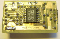
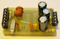
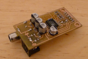
The AD724 is only available in an SMD package. You can choose to make the entire PCB in SMD or use standard parts for the external components.
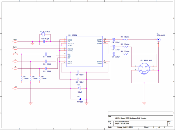
Schematic
The following schematics are configured for PAL TVs. If you are in an area where NTSC is in use, please see the note below regarding pinout changes.
Connections
The following diagrams show how to connect the S-VHS Modulator for all situations.
Diagrams for internal installation to follow.
Resources
The following files are the PCB and component position layouts to construct the circuit above:
File:AD724 Mod Layout.pdf - PCB Track Layout for full SMD version as seen in the third picture above.
NTSC
Pin 1 of the AD724 selects whether the output is in PAL or NTSC format. In the schematics and layouts above, pin 1 is grounded to select PAL, should you require NTSC, this pin needs to be disconnected from the ground and connected to a 5V signal and instead of the 4.433618 Crystal, you will need to use a 3.579545 Crystal.


